
4ft General Solvent Hood
Roger Robbins, Arnold Duenes
2/13/2006
Table of Contents
Introduction
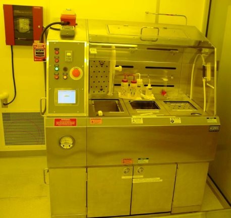
This document describes the Clean Room’s new 4 foot Solvent Hood from Leatherwood Plastics, Inc., Lewisville, Texas. This hood is intended to be used with solvents only, and not base solutions which tend to discolor the stainless steel. Because of the small size of this hood it is desired that only
one operation at a time be conducted in the hood.
Description
The Solvent hood is constructed of Type 304 stainless steel. The working surface components include a solvent sink that drains into a solvent catch can under the deck, an ultrasonic agitator built into the work deck and a standard DI water sink. They are built flush with the deck, and include stainless steel lids to increase the flat work surface area when the sinks are not in use. Each of the features has been
labeled for identification and proper use.
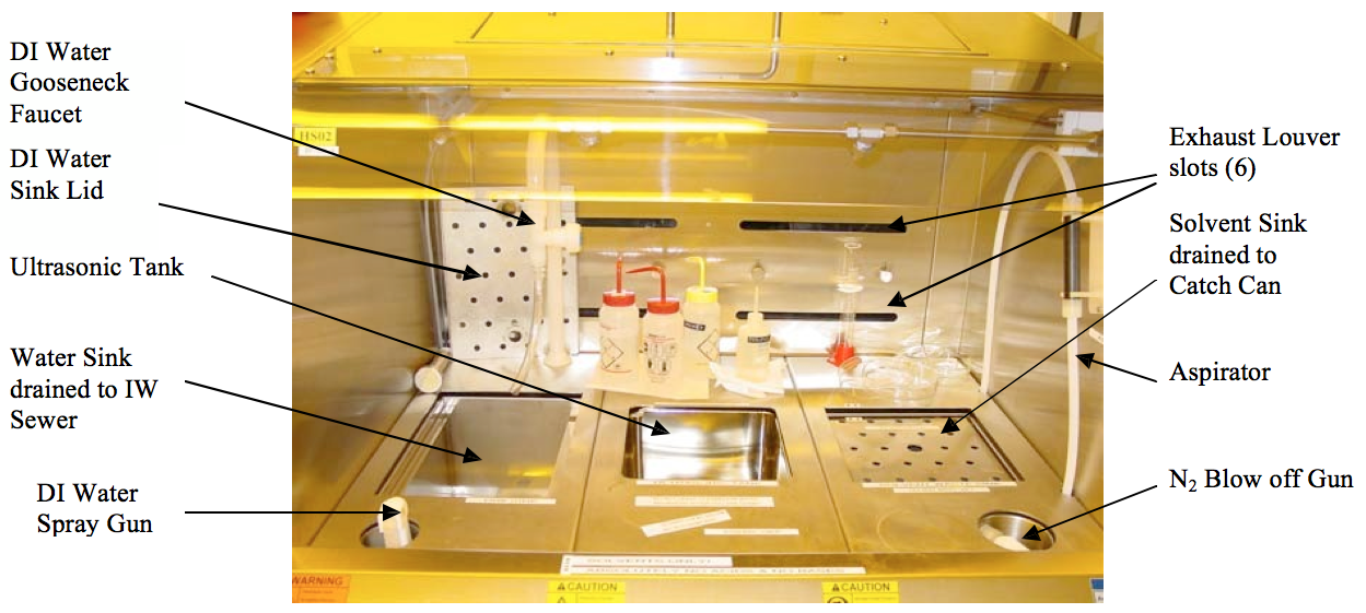
Figure 1. Photo of 4’ Solvent Hood showing the layout of components on the work surface.
The fire protection system consists of a major fire pull station that will set off the building alarm, and a local fire suppression system that will automatically detect and suppress a hood fire in the working area, below deck, and at the solvent waste canister with a CO2 extinguishing system. The photohelic exhaust pressure gauge has a sensor and relay that will shut off the hood if the exhaust fails. There is a standard red EMO button on the control panel that shuts down the hood in case of a local non-spreading emergency. The hood facilities are turned on and off with an “on” and “off” button on the control panel.
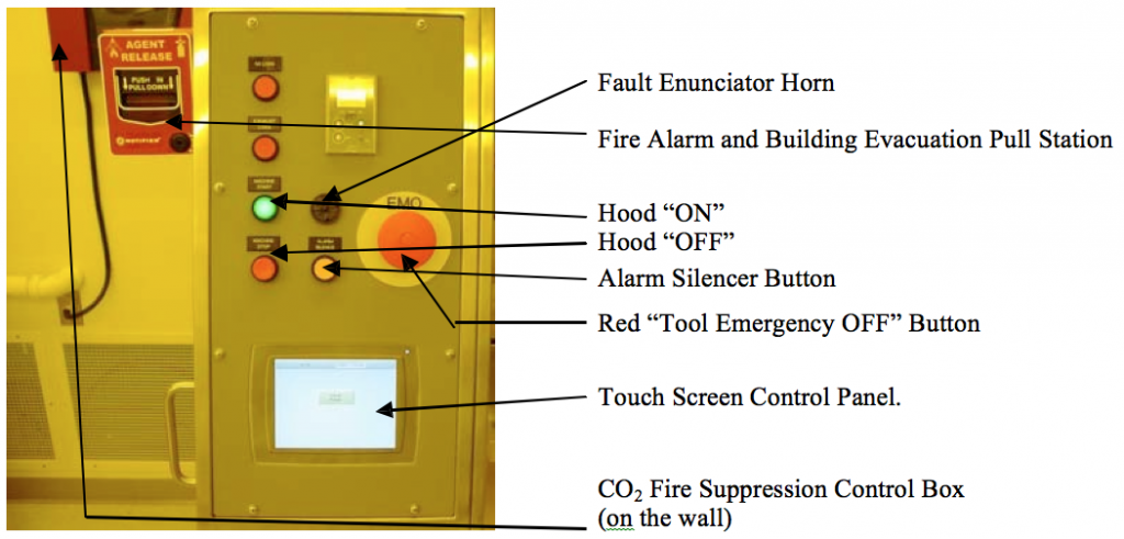
Figure 2. Safety alarm and shutoff switches
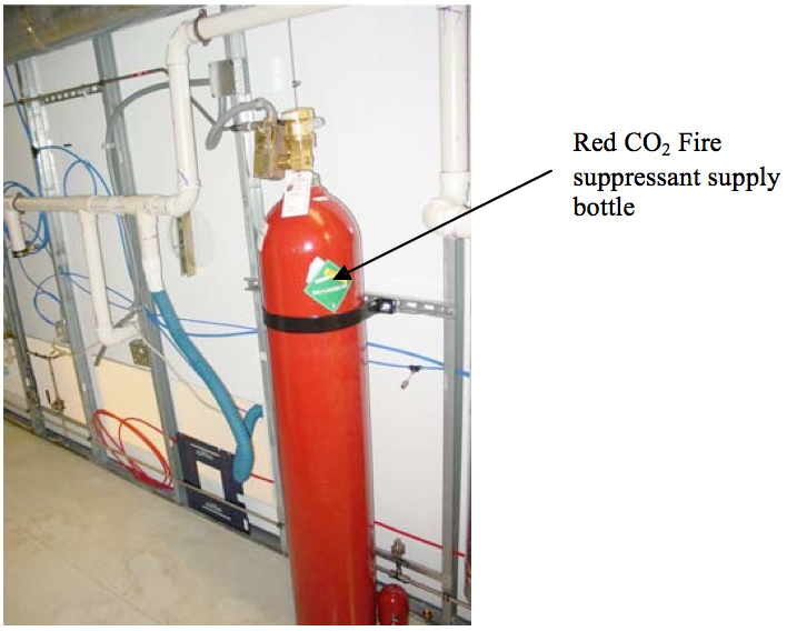
Figure 3. Red CO2 bottle for fire suppression is located in the service chase behind the hood.
The solvent-safe plastic canister seen in Figure 4 is the hood’s waste solvent collection canister. It is located under the hood behind the two doors a on the lower front panel. In this under-hood enclosure, there is a fire sensing and suppression system protecting the canister from causing a
disastrous fire. It attaches with “quick connect” connectors to the drain and exhaust lines. It also has a liquid level sensor that notifies the hood
operator that the canister is full and shuts off the hood drain if the liquid reaches the full level. The liquid level sensor is external to the canister as shown in Figure 5, so that the canister can be removed and emptied without having to deal with an internal level sensor.
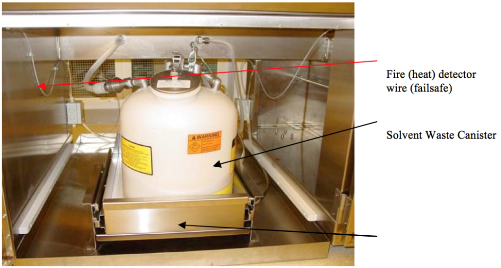
Figure 4. Waste Solvent Collection Canister under hood.
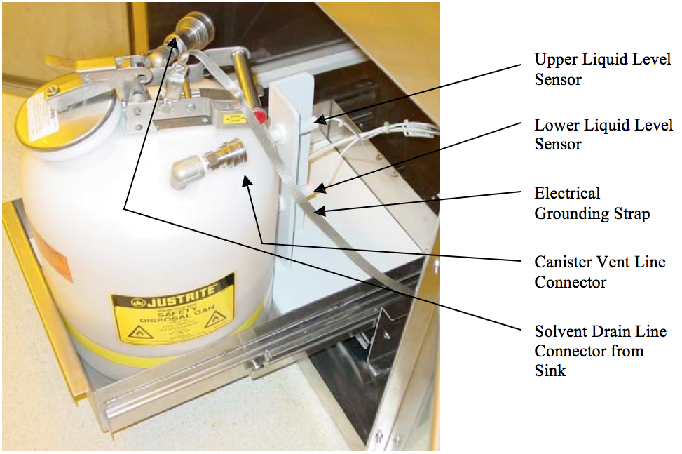
Figure 5. Solvent Waste Canister Level sensor system. Note the upper and lower liquid level sensors mounted on the angle plate at the rear of the canister. These sensors are fixed to the floor of the drawer and are separate from the canister.
The yellow fluorescent lamp is housed in a N2 purged box above the work surface and illuminates the work surface with a filtered light that will not expose optical resists. The bulb is changed by lifting the handle and replacing the bulb.
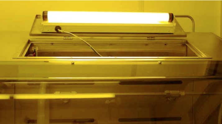
Figure 6. Location hood lamp under lift-up hatch in the roof of the hood. Note the yellow filter to prevent unintended exposure of optical photoresist.
The hood control facilities are located below the work surface and in a service panel on the left side of the hood behind the control panel. Figure 6
shows the insides of the control panel on the left side of the hood. There are no user controls located in these locked areas, so if a problem arises,
please call a Clean Room Staff member for help.
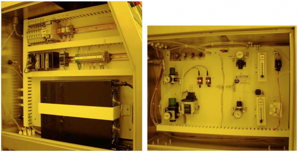
Figure 7. Hood Control (left) and plumbing control facilities (right). The large dark box in the lower middle of the left photo is the ultrasonic tank power supply.
The following discussion outlines the work area features, tools and intended use.
The hood control panel is located on a sloping face at the left end of the hood. It consists of control buttons, indicator lamps and emergency buttons and the main hood control touch screen. Figure 6 points out the features of interest.

Figure 8. Hood Control Panel on left side of hood.
The solvent sink is designed as a convenient place to clean items with solvent and allow the waste to drain into the catch can. Petri dish develop and rinse operations can also use the solvent drain feature of this sink without having to save and store the waste for later disposal. This sink is
located on the right hand side of the work surface and drains into the waste solvent can under the hood. There is however a valve in this drain line that closes when the waste solvent canister is detected to be full. When the waste solvent tank trips the full sensor, the annoying alarm buzzer will sound. Please notify a clean room staff member when this occurs. Both the amber light and the audio sensor can be silenced with the Alarm Silencer button on the control panel, but when you try to open the sink drain valve, the alarms go off again. Figure 5 shows the solvent catch can.
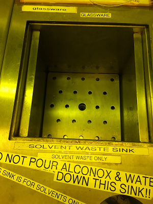
Figure 8. Solvent Sink with valve controlled drain. Waste solvent drains into solvent waste can under the bench.
The ultrasonic tank is located next to the waste solvent cup sink. It is recessed under the surface and covered with a lid. There is a handle in its center to lift it away from the tank. The tank should be filled with water as an energy transmission medium and the substrates requiring agitation
should be floated on the water inside a Petri dish filled with appropriate solvents to satisfy the purpose of the agitation. The water level in the tank is monitored by a pressure sensitive bubbler so that if the water level drops below the end of the bubbler tube, the system will shut off the ultrasonic tank power to protect the ultrasonic transponders and set off the annoying alarm. You can silence the alarm by pressing the yellow “Silence Alarm” button on the hood control panel at the left end. This alarm condition is also noted on the hood control panel with a brightly shining red light next to the appropriate sign. Also, because of the presence of the bubbler tube, the lid to the tank is slotted on opposite corners to avoid collision with the tube. There is a handy arrow marker on the lid and the working deck denoting the proper orientation of the lid.
The power level of the ultrasonic transponders is set at about 2/3 of maximum. If you need a different power setting, please contact a staff member for adjustment and notify him when you have finished so the power level can be returned to its normal setting.
When you finish with your operation at the hood, please clean up. Pick up all the wipes and put away all the glassware.
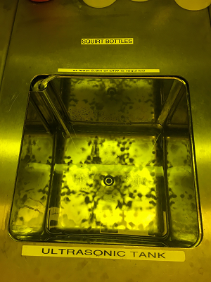
Figure 9. Ultrasonic tank showing the bubbler level monitor. Bubbles should be emitted from the tube at a rate of about 3 per sec. when the water level is at the proper height. Remember to clean up after completing your operation – note reminder signs.
Hood Tools
Nitrogen Blow off Gun
The Nitrogen blow off gun is located on the front right hand side of the working deck. It has a 0.3 micron particle filter in the nozzle and produces a soft-blow N2 stream. Take care in handling them because the spiral hose is quite stiff and may cause spills if it gets loose or springs back or rakes across the deck.
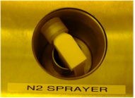
Figure 10. N2 blow-off gun located on the right hand side of the working deck.
DI Water Spray Gun
The De-Ionized water spray gun is situated on the left side of the hood just below the large water sink and is used to rinse substrates as required.
The spray gun has a really stiff spiral recirculating coaxial feeder tube supplying water. The recirculating feature keeps the DI water from stagnating and allowing bacteria to grow, thus causing particles to appear. Beware, this tube is very stiff and springy and can cause spills if it slips from your gloved hand. Grip the handle firmly and aid the tubing when pulling and returning the sprayer to its cubby hole.
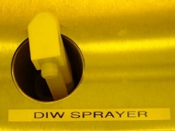
Figure 11. DI recirculating water spray gun
Solvent Aspirator
The solvent aspirator is basically a Venturi vacuum-assisted-start siphon. The aspirator is located and stored on the right hand wall of the working area as shown in Fig 12. This is a waste solvent drain tool to siphon solvent from a container. It operates by sending high pressure N2 through a Venturi suction device that pulls fluid into the aspirator tube with a very slight vacuum created by the Venturi. When the fluid fills the suction tube to a level below the fluid level in the container that requires draining, the N2 is cut off and the solvent then is siphoned into the solvent drain canister. BEWARE: When the N2 is first started, it puffs out the end of the aspirator tube and if you have it submerged in your waste solvent, then it will cause the solvent to violently erupt and splash all over everything in the hood. Also, when you first turn on the N2 to start the aspiration, there may be some previously aspirated fluid that flies out the end of the tube. Therefore, to start the aspiration, point the end of the aspirator tube into a sink, push the “Aspirator” button and then after about 3 to 5 seconds, place the end of the tube into the waste solvent and the siphoning action should drain your container. The Aspiration air flow can be stopped by pushing the “Aspirator” button again (toggle). This will create a pure siphon action which will be faster than if the aspiration airflow remains on. If you allow air to get into the tube during the siphoning stage, the siphoning action may stop and you will have to start all over.
The aspirator will usually not be needed for Petri dish and small beaker use because the (solvent) contents of small containers can be easily poured into the solvent sink which drains directly into the waste solvent canister.
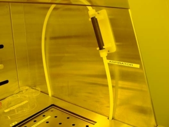
Figure 12. Solvent Aspirator storage next to the solvent sink.
Touch Screen Control
The touch screen control panel speaks directly to the controller computer that drives the hood functions. The following figures show all the screens that are important in operating the hood.
If the hood has experienced a power loss and you have to start up operations from the top level screen, it will require a password as shown in Figure 13 (A). Touch the button and a new screen will appear as in Figure 13 (B). Enter the secret password “UTD” for permissions and touch the enter button in the lower right corner of the entry screen. Higher levels of permissions have different passwords held by the staff. If a function you need results in an “Access Denied” message, please call a staff member.
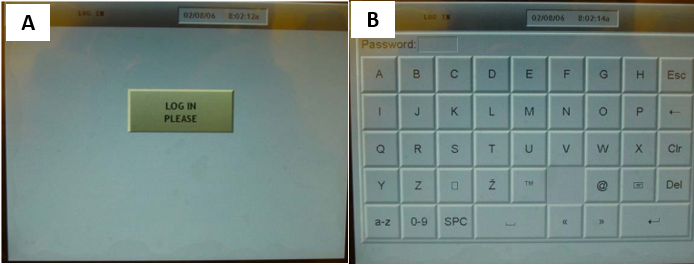
Figure 13. Login screen (A). Push the button and a new screen will appear as in Figure (B).
Select Options

Figure 14. Top level operation screen. The “Cycle Timers” and “Tool Manual Control” and “Alarm” buttons are the only operator accessible buttons on this screen.
There two cycle timers for this hood. On e controls the time that the ultrasonic agitator is on, and the other is just a general timer for a second
process. The ultrasonic timer and generator need to be enabled before the ultrasonic tank can begin operation on the timer. Just press on the enable icon at the far left of the screen. Then enter the time by pressing the number windows and entering the time in the popup keypad. Hit “START” to begin agitation. The agitation will end when the time is up.
The general timer operates the same way, except it does not need an enable command.
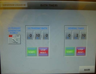
Figure 15. Cycle timer screen showing ultrasonic enable and bath timer as well as a second independent timer.
Tool Manual Control
The tool manual control screen is shown in Figure 17. There are three functions controlled by this screen. The drain valve for the ultrasonic bath is toggled open and closed with the left hand touch pad. The solvent drain valve is toggled open and closed by the right hand touch pad. And in rare cases when the aspirator needs to be used, the top right pad will toggle it on and off.
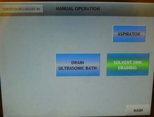
Figure 16. Manual operation screen showing the three operations available on this screen.
In the Supervisor level of permission, one can monitor the condition of various controller output and input states. This is used for manual control
during debug operations. It is reserved for staff and vendor use.
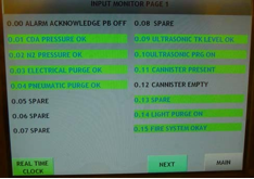
Figure 17. Input status screen for staff debug.
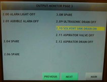
Figure 18. Output status screen.
The alarm log screen keeps a history of alarms the hood has seen in the past. This is usually only useful to staff in debug mode.
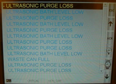
Figure 19. Alarm log screen showing recent alarm history.
Rules of Operation
Now that the hood facilities and capabilities have been described in writing, here are a few rules of operation to keep the hood in top shape as well
as keeping it in a safe condition:
- Only one experiment at a time in this hood.
- Please read all labels and instructions prior to using the solvent hood
- Before starting any operation, fill out the standard chemical form with the chemical in use, your name, date and time, and contact information.
- Take your time, be careful and focus on your operation in the hood – minimize distractions.
- Remember the difficulties inherent in the aspirator and use it carefully.
- When you are finished, clean up your work area and return all the tools you have been using to their proper place. – especially papers and rags.
- Dispose of SOLVENT waste in the solvent cup sink.
- Do not pour solvent waste into the water sink.
- Never pull the fire handle unless you actually see fire in the hood area.
Summary
This document has briefly outlined the description and features of the new 4 foot General Purpose Solvent Hood. Things to note are: 1) Use this hood for Solvent operations ONLY – NO BASES, 2) The ultrasonic tank must have a minimum height of water in the bottom before it will operate, 3) Read the rules of operation below.
Note that the solvent aspirator is a siphon and puffs N2 out the end when it starts, (start aspirator before putting into solvent); fill the tube to a level below the surface of the waste solvent to start the siphoning action. Since there is a large solvent sink, you probably will never have to use the aspirator.
Appendix A
Airflow measurements in linear ft/min were taken at numerous points as shown in Figure A1. The main exhaust duct damper valve is set at about 45 degrees. The measuring points are labeled in the figure and refer to entries in the following Table A1 listing the values.
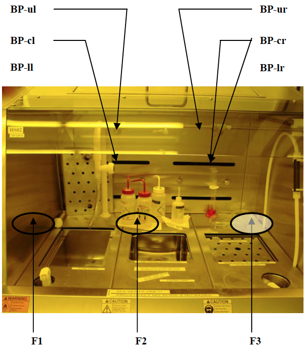
Figure A1. Location of air velocity measurements
Table A1
Air Velocity Measurements
| Location | Velocity (ft/min) |
| F1 | 174 |
| F2 | 135 |
| F3 | 135 |
| BP-ul | 1230 |
| BP-cl | 1240 |
| BP-ll | 1350 |
| BP-ur | 1300 |
| BP-cr | 1170 |
| BP-lr | 1375 |