
AJA Magnetron Sputter System
Arnold Duenes, Gordon Pollack
January 27, 2006
Table of Contents

1. Introduction
This document describes operational and maintenance procedures for the AJA Magnetron Sputter System; UTD Cleanroom Tool ID: MS03. This tool is used to deposit metallic and insulating films (i.e. Aluminum, Nickel, Titanium, SiO2) onto a substrate material such as Silicon by sputtering from up to four target materials.
This document is limited to directions on how to safely operate MS03 and includes staff procedures for safely venting the main chamber to atmosphere for target replacement. Detailed information on tool installation, startup, preventative maintenance, and failure recovery can be found in the AJA Installation & Operation Manual that was provided with the tool.
This document is intended for cleanroom users and staff personnel.
Definitions & Process Terminology
Angstrom: (Å) A unit used to measure very small lengths, such as wave length. Equal to 10-10 m
Atmosphere: Unit of pressure corresponding to standard atmospheric pressure. It is taken as the pressure that will support a column of mercury 760 mm high. It is also equal to 1.013 * 105 Pa
Base Pressure: The lowest achievable pressure attained after the vacuum chamber has been pumped down (to lower pressure), typically for several hours
Chamber: The part of the vacuum system containing the DC and RF magnetrons, wafer holder, heat lamps, and thickness monitor.
HiVac: “High Vac” is a term used to describe a “good” vacuum (10-6 – 10-9 torr), in which most of the gas has been removed
HiVac Pump: Pump that functions in the high vacuum range
HiVac Valve: Large diameter valve that is placed between the vacuum chamber and the vacuum pumps; used to isolate the chamber from the pumps when it is necessary to work inside the chamber
Roughing Pump: A pump which functions in the rough vacuum range 760 0.001 torr
Substrate: The material onto which a film is sputter-deposited
Target: The source of material to be sputtered. Targets are 2” in diameter and 0.25” thick except for magnetic materials, which are 0.125” thick.
Torr: Unit of pressure. 1 torr = 1 mm of Hg = 133.3 Pa
Vent Valve: The valve used to bleed Nitrogen in the chamber to bring it to atmospheric pressure
Wafer: A thin slice of semiconductor (such as silicon) used as a substrate for an electronic component
2. Overview
In the sputtering process gas ions (typically Argon) are created in a plasma and accelerated into a target material. The impacting ions cause material to be removed (“sputtered”) from the target and deposited on a substrate in the vicinity of the target. To enable ignition of the plasma, the gas pressure is typically maintained in the range of 3-50 mtorr. Due to natural cosmic radiation, there are always some positively charged gas ions available to ignite the plasma. In DC-sputtering a negative target potential up to several hundred volts is applied to accelerate the positively charged ions to the target.
The impacting ions also create energetic secondary electrons that cause further ionization of the gas. To increase the gas ionization rate even further, a ring of magnets is placed below the target to trap and circulate the secondary electrons over the target. This is process is referred to as magnetron sputtering. All four sputter guns in MS03 use magnetron sputtering to increase the gas ionization rate and, hence, the deposition rate.
DC-sputtering is limited to conducting materials like metals and doped semiconductors. The reason is that bombardment with positive ions would quickly charge up the surface of an insulating target material and cause the ion current to die off. Instead, for insulating materials, a radio frequency AC-voltage is applied to the target to prevent the charge buildup associated with DC-magnetron sputtering. This technique is called RF-magnetron sputtering. In MS03, two of the sputter guns are DC-magnetrons and two are RF-magnetrons.
In addition to Argon, Nitrogen and Oxygen are available in MS03 for use in reactive ion sputtering applications. In reactive sputtering a reactive gas chemically combines with the target material to form a different material. To further enhance reaction rates or change the morphology of the deposited films, the substrate holder can be heated up to 850 C. MS03 also has the capability to apply RF-power to the substrate holder to sputter clean samples before deposition. The substrate holder can also be rotated during deposition to improve film uniformity. Substrate rotation is recommended for room temperature depositions, and is mandatory for heated depositions.
3. Safety
All users must be trained and qualified by cleanroom staff before operating the MS03 sputter system.
Surfaces within the load-lock may be hot due to substrate heating. Do not touch surfaces without cooling the substrate holder to room temperature after a heated run.
Wear clean gloves when handling components in the load-lock chamber to prevent contamination of the substrate holder.
Intense light will be emitted from the plasma. Always close the viewport shutter when making a run to protect your eyes and prevent deposition on the viewport window.
4. Hardware Specifications
4.1. Process Gases: Ar, N2, O2
4.2. DC-Magnetron: 500 Watts maximum
4.3. RF-Magnetron: 300 Watts maximum
4.4. Substrate Temperature: 25C to 850C
5. Operating Procedures
5.1.1. Mount Sample: Using clean gloves to prevent chamber contamination, mount a clean 4” substrate on the sample holder. Use the four washers and machine screws to hold the sample in place. If the machine screws become difficult to turn, please notify staff, who will replace the screws.
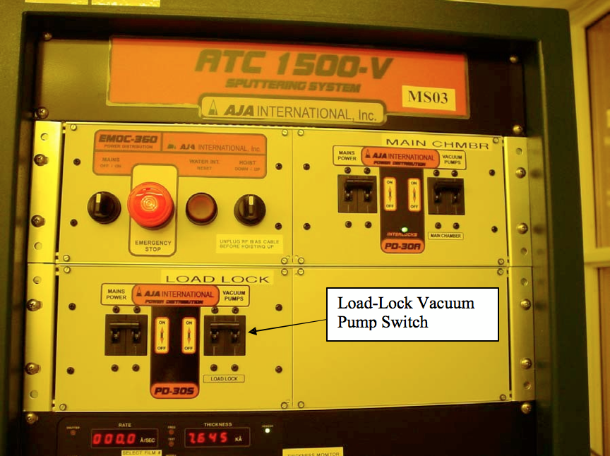
Figure 1. Location of Load-Lock Vacuum-Pump Power Switch
5.1.2. Vent Load-Lock Chamber: Vent the load-lock chamber by turning off the load- lock turbo pump power switch labeled Load-Lock Vacuum Pumps. This will shut off the turbo and mechanical pumps and activate the turbopump’s delayed vent valve. See Figure 1 for the location of the switch.
5.1.3. Open Load-Lock Chamber: Once the load-lock chamber reaches atmospheric pressure, lift the aluminum load-lock cover, and place it face down on the four rubber pads on the table top.
5.1.4. Load Sample: Position the substrate holder on the transfer arm. It is critical that the sample holder is oriented correctly on the transfer plate to facilitate easy insertion of the three blades of the propeller shaft into the recesses of the sample holder. Figure 2 shows correct orientation of the sample holder on the transfer arm.
Note that the four machine screws with the washers that hold the sample are not in contact with the transfer arm.
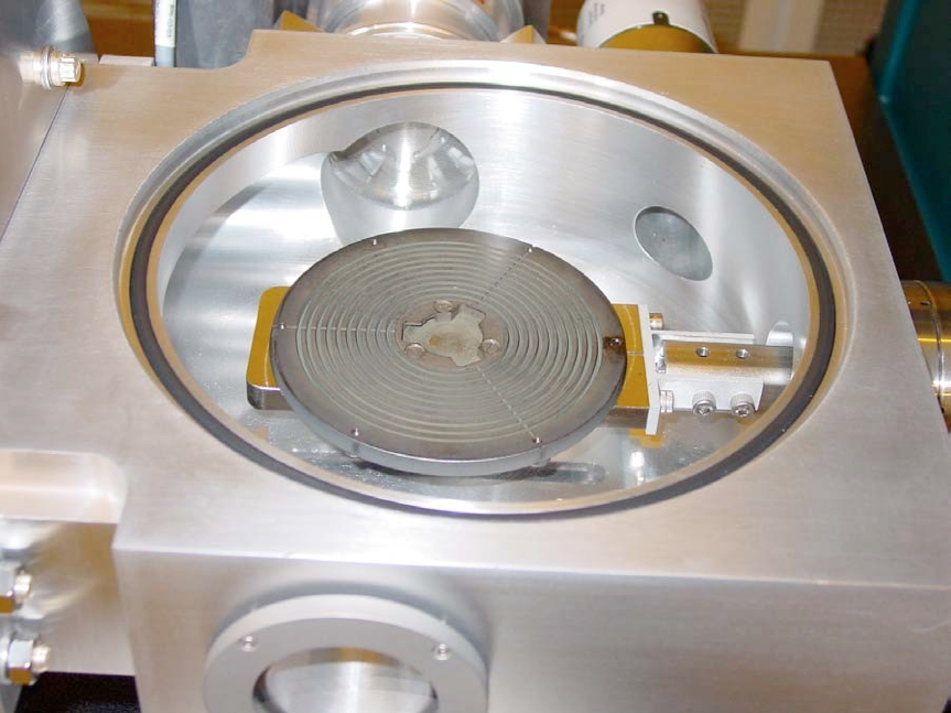
Figure 2. Correct Orientation of the Sample Holder on the Transfer Arm.
5.1.5. Replace Cover: Place the aluminum load-lock cover uniformly on the load-lock transfer port.
5.1.6. Pump Chamber: Turn on the Load-Lock Vacuum-Pump power switch to pump- down the load-lock chamber. Please refer to Figure 1 for the location of this switch. The pump-down process should take about 5-10 minutes. Once the load- lock chamber pressure is below 1.0E-5 mbar, it is safe to transfer the sample into the main chamber.
5.1.7. Open Gate Valve: Once the load-lock chamber pressure drops below 1.0E-5 mbar, the transfer gate valve can be safely opened. Open the gate transfer valve by turning the transfer valve crank counter-clockwise until it stops.
5.1.8. Position Transfer Arm: Look through the viewport, and use the joystick to raise the substrate holder height to allow enough clearance for insertion of the transfer arm. With your right arm gently push the transfer arm to the left until it hits its mechanical stop.
5.1.9. Engage Substrate Holder: Look through the viewport, and move the joystick left or right to rotate the propeller blades to align with the recessed blade mount on the sample holder. Figure 2 shows the orientation of the recessed blade mount. Next, move the joystick down to gently lower the propeller blades into the recess on top of the substrate holder. Lower the blades into the substrate holder until a slight bend in the transfer arm is detected. Next, manually rotate the propeller blades 30o clockwise to engage the sample holder mount. Figure 3 shows the location where the propeller shaft can be rotated manually.
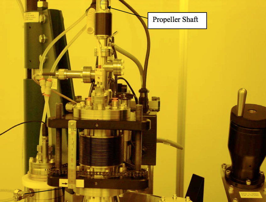
Figure 3. Propeller Shaft Vertical Alignment Mark and Manual Rotation Point.
5.1.10. Extract Substrate Holder: Look through the viewport, and move the joystick up to lift the substrate holder from the transfer arm. Raise the substrate holder to the desired process distance. The default process distance is indicated by the alignment mark on the steel ruler mounted next to the bellows.
Slowly move the transfer arm out of the main chamber until it comes to rest against the mechanical stop.
5.1.12. Close Gate Valve: Close the transfer gate valve by turning the handle clockwise. Just before the gate valve is completely closed, an audible click should be heard.
5.2.1. Start Sample Rotation: Begin substrate rotation by slowly turning the speed adjust knob on the rotation controller to the desired level. It is important to visually check that the sample rotation is smooth and level. If this is not the case, the propeller blades may not be adequately locked into the sample holder. A rotation setting of 50% is good for most runs. Higher rotation rates should be used for short duration runs, i.e. less than 5 minutes, to improve the uniformity. Figure 4 shows the location of the speed adjust knob.

Figure 4. Position/Rotation Control, Temperature Control, and Load-Lock Vacuum Gauge.
5.2.2. Activate Substrate Heater: The SHQ-1SR substrate heater controller is capable of heating the Inconel sample holder up to a temperature of 850C. The substrate holder must always be rotated when using the heater to insure that the sample holder is uniformly heated. To operate the heater, the heater controller power switch and the rotary heat switch must be turned on. Although the heater can be operated in manual mode, it is recommended that the heater be operated by the control computer.
5.2.3. Start the Deposition Process: Although processes can be run manually, it is recommended that processes be created and run remotely using the process control computer. In order to do this, the VAT controller must be in Remote mode. To start the process, click on the Run Process button and Open the desired process recipe. A dialog box will then appear with a short checklist. If all checklist items are satisfied, click the OK button, which will start the process. Click Cancel if all checklist items are not satisfied. At the end of the process, a dialog box will appear indicating that the process has been completed.
5.3.1. Turn Heater Off: Turn off the substrate heater by turning the Heat switch on the heater controller counter-clockwise to the Off position.
5.3.2. Stop Sample Rotation: Turn the sample rotation knob counter-clockwise to stop sample rotation. Next, use the left-right joystick controller to rotate the sample holder back to the orientation it had when positioned on the transfer arm.
5.3.3. Open Gate Valve: Check to make sure that the chamber pressure in the load-lock is below 1.0E-5 mbar before opening the gate valve. Open the gate transfer valve by turning the valve crank counter-clockwise.
5.3.4. Position Transfer Arm: Look through the view-port, and use the joystick to raise the substrate holder to allow enough clearance for insertion of the transfer arm. Gently push the transfer arm to the left until it hits its mechanical stop.
5.3.5. Disengage Substrate Holder: Look through the view-port, and use the joystick to gently lower the sample holder onto the transfer arm. Lower the substrate holder until a slight bend in the transfer arm is detected. Next, manually rotate the propeller blades 30o counter-clockwise to disengage the propeller blades from the sample holder mount. Figure 3 shows the location on the propeller shaft where the propeller can be turned manually to disengage the sample holder.
5.3.6. Retract the Transfer Arm: Slowly move the transfer arm out of the main chamber until it comes to rest against the mechanical stop.
5.3.7. Close Gate Valve: Close the manual transfer gate valve by turning the handle clockwise. Just before the gate valve is completely closed, an audible click should be heard.
5.3.8. Vent Load-Lock Chamber: Vent the load-lock chamber by turning off the Load- Lock Vacuum-Pump power switch. This will shut off the turbo and mechanical pumps and activate the turbopump’s delayed vent valve. See Figure 1 for the location of the switch.
5.3.9. Open Load-Lock Chamber: Once the load-lock chamber reaches atmospheric pressure, lift the aluminum load-lock cover, and place it face down on the four rubber pads on the table top.
5.3.10. Remove Sample Holder: Carefully remove the sample holder from the load-lock chamber. Warning, the substrate holder may be hot! If it is hot, wait until it cools down before removing.
5.3.11. Replace Cover: Place the aluminum load-lock cover uniformly on the load-lock transfer port.
6. Maintenance Procedures
6.1.1. Close laptop (safety precaution)
6.1.2. Switch VAT Controller to LOCAL mode
6.1.3. Close Transfer Gate Valve (rotate CW until it stops)
6.1.4. Close VAT Gate Valve, and turn OFF M/C pumps (flip breaker down)
6.1.5. Wait for M/C Turbo pump to whine down (listen for it)
6.1.7. Wait for 1 ATM to be achieved (760torr : 1.0133bar)
6.1.8. CLOSE manual vent valve (do not over tighten)
6.1.9. Unplug RF Bias cable and move out of the way
6.1.10. Remove T-pin
6.1.11. Hoist UP: use your left hand to carefully guide the assembly up
6.1.12. Stop hoisting before reaching upper limit
6.1.13. Confirm there is enough clearance for assembly to swing left
6.1.14. Slowly swing left (enough to clear M/C open space)
6.2.1. Inspect M/C O-ring and insure it is seated properly.
6.2.2. Position assembly roughly over M/C, and then hoist down approx. 3in.
6.2.3. Replace T-pin (it should fall into guiding hole) to hold assy. in place.
6.2.4. Hoist DOWN until making full contact with M/C base.
6.2.5. Re-connect RF Bias cable.
6.2.6. OPEN VAT Gate Valve.
6.2.7. Turn ON M/C pumps.
6.2.8. Monitor pump down pressure.
6.2.9. Insure green Interlock LED is on.
6.2.10. Turn ON Ion Gauge.
6.3. Bringing System Up after Complete Shutdown
6.3.1. Turn on the chiller. Insure that chilled water is running @ 18C, 62psi.
6.3.2. Insure N2 vent gas is flowing @ 2-7 psi.
6.3.3. Insure that Transfer Gate Valve is fully closed (rotate clockwise).
6.3.4. Turn ON system by turning the EMOC-360 Mains switch CW.
6.3.5. If OFF, turn ON the Main Power breakers for M/C & L/L power supplies. (Note: Do not turn on the Vacuum Pump breakers yet)
6.3.6. Check the M/C vacuum pressure; it should be in the -1 to -3 torr range (if there’s been an unexpected pressure loss, it’s possible there may be a leak).
6.3.7. OPEN manual vent valve.
6.3.8. Wait for 1 ATM to be achieved (760torr: 1.0133bar).
6.3.9. CLOSE manual vent valve (do not over tighten).
6.3.10. If not already in local mode, switch the VAT Adaptive Pressure Controller to LOCAL mode.
6.3.11. Open VAT Gate Valve.
6.3.12. Turn ON M/C pumps.
6.3.13. Monitor pump down pressure.
6.3.14. Insure green Interlock LED is on.
6.3.15. Turn ON Ion Gauge.
6.3.16. Turn ON remaining power supplies and controllers (this includes the 3 RF power supplies & controllers, the 2 DC power supplies & controllers, and the heater controller).
6.3.17. Power ON the PC and start the AJA program.
6.3.18. Insure that the VAT position is 1000 (OPEN position), and then switch to REMOTE on the VAT controller.
6.3.19. End of Procedure.