Base Hood Operations
Roger Robbins
11/1/2005
Table of Contents
Introduction
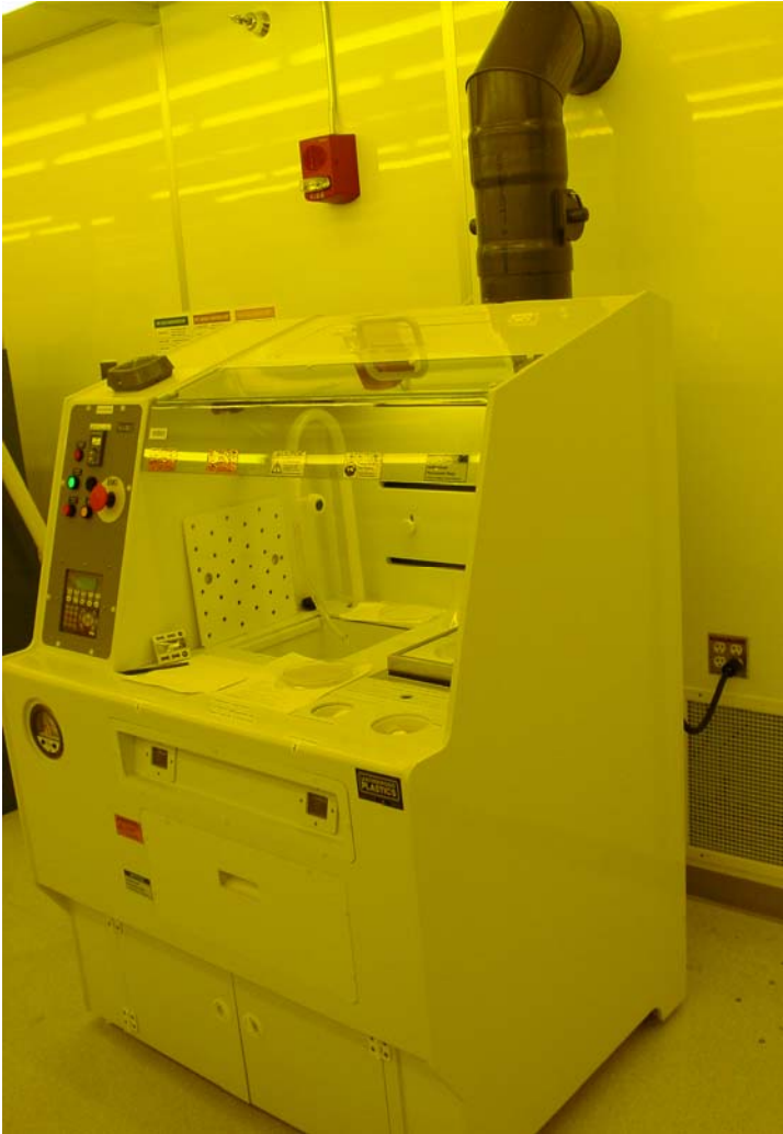
This document describes the Clean Room’s 4 foot base hood from leatherwood Plastics, Inc., Lewisville Texas. This hood is intended to be used with bases only, especially no solvents. It is a plastic hood with a DI water sink and a hotplate built into the working surface. Normally, it is used for optical resist development. It is small and can support only one operation at a time.
Description
The base hood is constructed of a chemical and fire resistant white PVCC plastic, with a 3 by 2.5 foot perforated work surface including a DI water sink with gooseneck faucet and an imbedded manual hotplate. There is a thermocouple temperature probe for measuring the temperature of your working medium on the hotplate. There is an ergonomic sloping control panel on the left side that houses control functions for the hood. The lighting is provided as filtered yellow light that will not expose optical resists. The hood is exhausted by a 10 inch plastic exhaust line that leads to a chemical scrubber on the roof of the building. The exhaust pressure is monitored by a photohelic pressure gauge which will set off the alarm and shut down the hood if the exhaust pressure is lost. The sink drain leads straight to the chemical drain system (acid drain line). There is a Nitrogen blow-off gun on a coiled line embedded in the work surface along with a DI water spray gun also on a coiled line. These major features are shown in Figure 1.
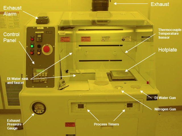
Figure 1. Base hood, 4 ft, showing major hood features.
Feature Details
The control panel is shown in Figure 2, and supports the microprocessor keypad/display, the Emergency Off button (EMO), and the DI water resistivity readout, along with the machine start/stop buttons and a loss-of-exhaust light.
The hood has a recirculating de-ionized water plumbing system to prevent stagnant water from growing microorganisms and contaminating the purity of the water. Ther is a monitor readout of this condition at the top of the control panel that displays the resistivity of the water in meg ohms. The nominal value of good DI water is 18.1 meg ohms or better. If you notice that the value has slipped into the 17 meg ohm level or lower, please notify the clean room staff and if this would impact your work, discontinue using the water.
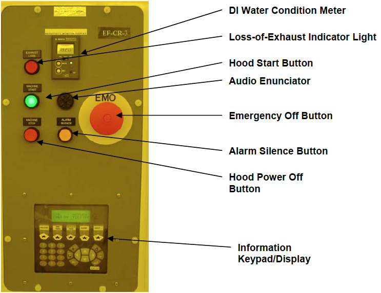
Figure 2. Hood Control Panel
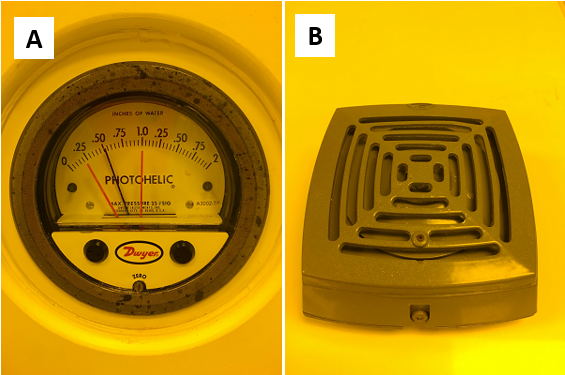
Figure 3. Photohelic Exhaust pressure gauge (A), and alarm horn (B)
The photohelic pressure gauge, Figure 3, measures the exhaust pressure in the exhaust line above the hood and if the pressure falls out of the acceptable range, it will trigger the alarm horn, Figure 3, to complain very loudly and the red alarm light on the control panel to light up, Figure 2. If this happens, quickly bring your work to a safe conclusion and discontinue the use of the hood. Also immediately notify clean room staff. There may be a general loss of exhaust requiring clean room evacuation. Follow staff direction.
The Green “HOOD START” button on the control panel turns on the electricity to the hood functions. The Red “HOOD STOP” button turns off “most” of the electricity to the hood. (Fire suppression power is left on and can only be turned off by the main disconnect). The hood is generally left “ON” all the time. This control is generally used when service is required.
The Emergency Off Button is used if the hood is having an electrical problem that portends of immediate emergency. If there is smoke coming from the insides or the hotplate is seriously overheating, please don’t hesitate to use this button. If you have had to push the EMO button, please notify Clean Room Staff immediately!
The audio enunciator is a piezoelectric beeper that announces either a non-emergency fault or the completion of a timed event. There is a convenient yellow alarm silencer button which you can use to cause immediate secession of the annoying beeps. However, please make sure that the cause of this alarm is corrected before leaving the hood.
Hood Controller Keypad/Display
This is a simple controller with very few functions. It mainly allows the user to set the time on the two timers and see the temperature on the thermocouple probe.
The time is set by pressing the star key under either the “sink timer” or the “hotplate timer” and then either entering the times from the numeric keypad or pressing the up or down arrows in the oval keypad. The alarm key brings up the alarm screen which displays the current and last few alarm messages.
Press the “Process” key to see the temperature of the thermocouple temperature probe.
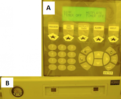
Figure 4. Controller keypad/display and timer start/stop keypads under the work surface on the front.
The hotplate, shown in Figure 5, is a simple manual stirring hotplate with local controls located under the removable panel just in front of the hotplate. There is a protective skirt around the hotplate heating surface to protect the hotplate from accidental spills into the sunken hotplate recess just below the hotplate heating surface. This protects the hotplate itself from internal damage from chemical spills. However, in the event of an accidental spill onto the (cool) hotplate heating surface, quickly wipe off the chemical, re-wipe with a DI water wetted wipe cloth and finally dry it off. The local control knobs set the temperature and control the stirring magnet speed.
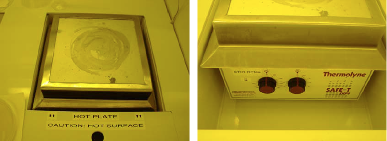
Figure 5. Stirring, explosion proof manual hotplate showing protective skirt and controls under the removable panel.
In addition to the hotplate itself, there is a separate thermocouple temperature probe available to measure the temperature of the medium that you are trying to heat. This probe is located in its holding fixture in the right rear corner of the hood. The temperature is read on the control panel by pushing the “Process” button.
The DI water sink is connected to the acid drain line and can accept waste base solutions with plenty of water dilution. The DI water faucet is a recirculating loop so that the water does not stagnate and grow microorganisms which contaminate the water with particles and organic material.
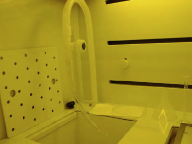
Figure 6. DI water sink and recirculating DI water faucet
Rules of Operation
Now that the features of the hood have been described, we will put forth a few operating rules.
Rules:
- When approaching the hood to start work, please notice the conditions in the hood and note any situational dangers. Either correct them or notify Clean Room Staff.
- Fill out the required Chemical use form
- Wear appropriate personal protective equipment:
- Safety glasses
- Appropriate gloves
- Chemical apron if necessary
- Only one operation at a time is allowed.
- Never place a chemical container on the floor.
- Always turn off the hotplate when your job is complete.
- You can slowly dump waste base solution into the sink but run plenty of DI water at the same time to dilute it. This is a serious issue, because strong bases and acids can react violently in the drain lines.
- When you are finished, clean up your work area and return all the tools you have been using to their proper place – especially papers and rags.
Appendix A
Air Flow measurements
Airflow measurements, in linear feet per minute, were taken with the main exhaust damper at full open. The slit damper in the back wall of the hood was also set at full open. Readings were taken at the center of the front sash opening and at the center of each of the slit exhaust openings on the back wall of the hood. The airflow measurements are shown in Table A1.
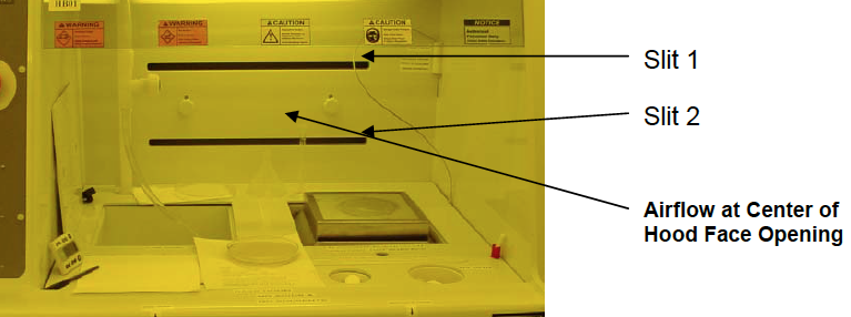
Figure A1. Face opening of Base Hood showing location of Air Flow measurements
Table A1
Air Flow Measurements*
| Location |
Flow (ft/min) |
| Face Center | 125 |
| Upper Slit | 1190 |
| Lower Slit | 1275 |
*Main Exhaust Damper full open
*Slit valves full open
Appendix B
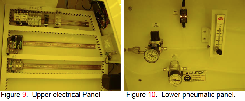
This appendix contains a collection of photos showing the hood infrastructure details for maintenance reference.
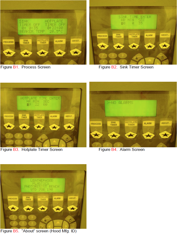
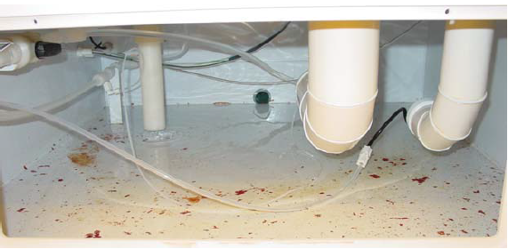
Figure B6. This is the sump where the water drains from the sink. Do not dispose of resist in this sink! Resist dissolved in developer is ok. NO SOLVENTS!!! (Solvents will dissolve the hood).
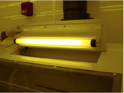
Figure B7. Access panel to change the Hood light.
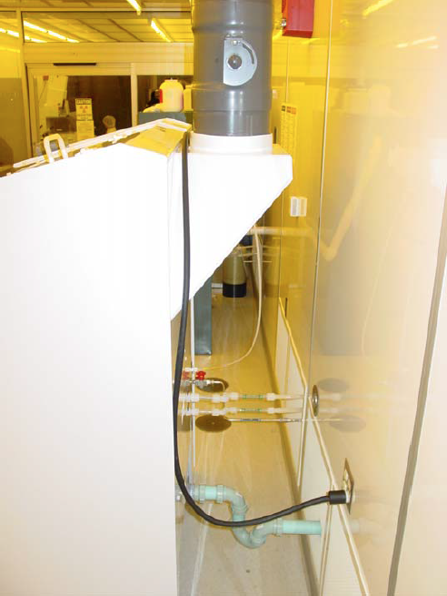
Figure 8. Facilities connections.