
Blue-M Oven Enclosure Airflow Balancing
Purpose
The “Blue-M” oven enclosure was built to consolidate the several ovens we have and also to capture any fumes that they might emit during a bake or sample exchange. This document records the enclosure exhaust airflow and the required oven placement configuration to achieve a balanced airflow sufficient to capture the fumes.
Discussion
The Blue-M oven enclosure is a structure of stacked, open front box enclosures on a frame with exhaust in the rear panel as shown in Figure 1. The exhaust entry in the rear panel is buffered with a baffle to distribute the air-capture across the back panel and ensure that there will be airflow around the sides of the Blue-M ovens so that when the door is opened, the fumes will be swept into the rear exhaust.
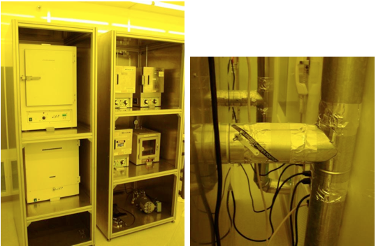
Figure 1. Blue-M oven enclosures, (left), and dampered exhaust connections, (right). Note the black diagonal label in the right photo depicting the proper angle for the damper handle.
In order to accomplish this, the airflow must be measured and balanced by adjusting the rear exhaust dampers and placing the ovens just so in the enclosure so that all sides of the little ovens will feel the exhaust airflow to a sufficient level. This means that the placement of the ovens is very important and they cannot be moved by users. Thus their locations have been marked and blocks positioned so that they cannot be conveniently moved.
Data
Airflow measurements were taken with a linear hot-wire anemometer as depicted in Figure 2. Measurements were taken across the face of each enclosure as shown in Figure 2, but localized measurements were taken at all edges of each oven and the airflow balanced so that each side had reasonably similar airflow. The Blue-M ovens were set 12 inches inside the enclosure and the large ovens in the left enclosure were set back 10 inches.
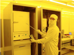
Figure 2. Hot-wire anemometer airflow measurement
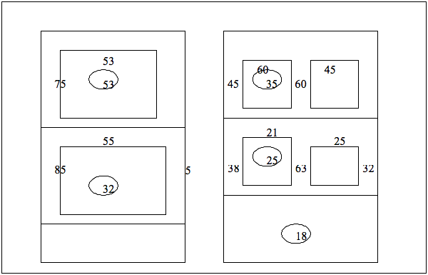
Figure 3. Horizontal airflow readings in linear feet per minute at indicated locations. Circled numbers represent the airflow speed in [ft/min] across the central face of each exhausted enclosure.
Exhaust Damper Settings
The following photos indicate the approximate angle for each exhaust damper per oven enclosure. The main dampers in the chase are wide open.
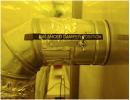
Figure 4. Upper left oven damper pos.
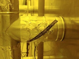
Figure 5. Lower left oven damper pos.
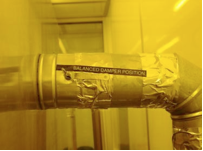
Figure 6. Upper Right
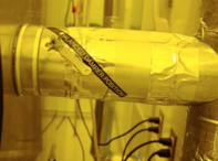
Figure 7. Middle Right
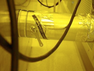
Figure 8. Lower Right (~off)
Oven Placement
The following figures show top-down views of the oven placement positions that achieved the above airflow readings. These ovens must not be moved; otherwise the airflow will be unbalanced and could fall below the minimum safe airflow to capture fumes from the ovens.
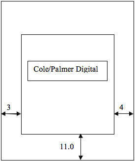
Figure 9. Horizontal placement; Left top shelf
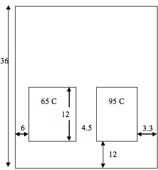
Figure 10. Horizontal placement, Right Top shelf
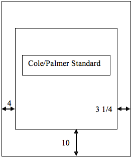
Figure 11. Horizontal placement, lower right
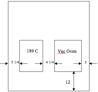
Figure 12. horizontal placement, Right middle shelf
Conclusion
The Blue-M oven enclosure airflow has been adjusted by exhaust damper positioning, and oven placement to achieve a reasonably balanced airflow so that fumes from the ovens will be captured by the exhaust and not spread out into the cleanroom. However, the enclosure
openings are too large to be efficient at this, and perhaps when the new thermocoup le temperature measurement system is installed, the shelving can be adjusted to reduce the size of the enclosure for the small ovens and increase the airflow velocity but reduce the exhaust volume flow rate.
Appendix A
Air Flow Measurements at NSERL Clean Room
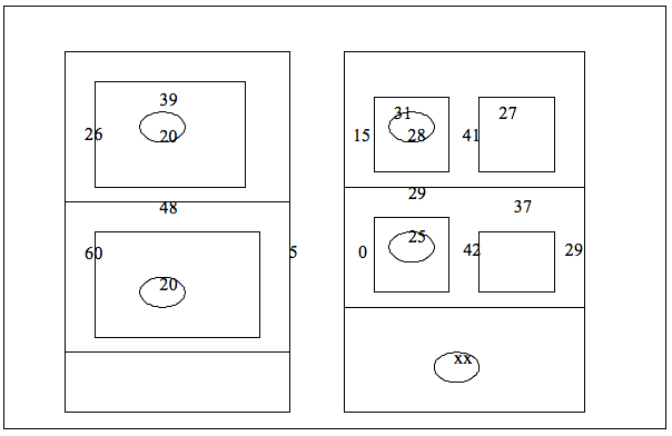
Figure A1. Revised Air flow measurements for the NSERL Clean Room