
Hummer VI
Brian Thomas
October 29, 2003
Table of Contents
2.1 Preliminary Checks before operating the system
3.1 Placing your sample in the chamber
1. Introduction
The purpose of this document is to explain how to operate the Hummer IV metal sputter deposition system. The usual purpose for utilizing this tool is to deposit a very thin layer of Gold onto an insulating sample intended for viewing in the Scanning Electron Microscope, (SEM). The reason this is important is that the SEM electron beam deposits electrons on the surface of an insulator sample causing “charging”. The electron field produced by the accumulated electrons deflects the electron beam probe, causing the image to distort, flicker, drift, or become bright or dark depending on viewing conditions.
This document is limited to describing the operational process of depositing Gold onto small SEM samples.
Hummer: The commercial name of a specific-purpose sputter deposition tool used to quench electron charging on SEM samples by coating the sample with a thin coat of Gold.
Charging: Accumulating of electrons on an SEM sample by the electron beam probe.
Electric field from this charge accumulation can disrupt the quality of the image by deflecting the electron beam.
Emission: A substance (or substances) discharged into the air
Substrate: The material of which something is made
Torr: Unit of pressure. 1 torr = 1 mm of Hg = 133.3 Pa
2. Overview
2.1 Preliminary Checks before operating the system
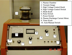
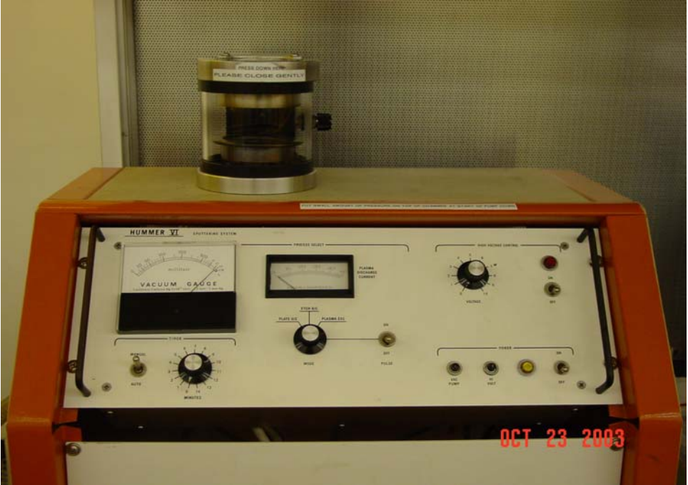
Figure 1. The Hummer VI Control Reference photo.
Before operating the Hummer VI, locate the High Voltage Control Knob, in the top right hand corner of the instrument panel, and make sure it is at zero. Secondly, make sure the High Voltage Control Switch, located just to the right of the HV knob is in the off position. The Mode knob should be set to Plate DC and the Pulse switch to the off position.
3. Procedure
3.1 Placing your sample in the chamber
- Gently open the lid of the plasma chamber
- Place your sample inside on the sample platen (Figure 2).
- Gently close the lid. Note if you slam the lid down, the sputter target will fall off. It is magnetically held to the top of the chamber.
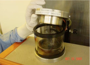
Figure 2. Opening the Plasma Chamber to insert a sample.
3.2 Striking a Plasma inside the chamber
- Turn on the Power switch
- Wait for the vacuum level to fall to around 150 millitorr.
- Flip the High Voltage control switch on
- Turn the High Voltage Control Knob until the Plasma Discharge Current meter reads 20 mA.
- NOTE: As you increase the voltage, current will not increase until a plasma is struck inside the chamber. This may not occur until the voltage is increased past the halfway point.
- NOTE: A plasma is struck when you see a pink glow inside the top of the plasma chamber. (Figure 3.)
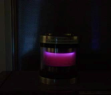
Figure 3. Plasma glow inside the chamber
- Begin timing the process as soon as a plasma is struck inside the chamber
- Normal Gold deposition takes about 1 – 3 minutes.
NOTE: Monitor the Plasma Discharge Current meter during the run. You may have to continue to adjust the voltage to maintain you set current.
- When the deposition time is up, turn off the High Voltage
- Also turn the High Voltage knob to zero
- Turn off the Power
- This will start the chamber to venting – vent requires several minutes.
- When the Plasma Chamber is at atmosphere, gently lift the chamber lid
- Carefully remove the cylindrical glass chamber
- Using a pair of tweezers, remove your sample
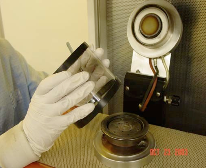
Figure 4. Removing the cylindrical chamber
4. Conclusion
We have described the procedure for coating an SEM sample with Gold for the purpose of quenching charging from the SEM electron beam probe. This process deposits roughly about 300 A, of Gold on a substrate.