
CEE Spin Coater/Hotplate Operation
Roger Robbins 10/07/2004
Table of Contents
Purpose
The UTD Clean Room has obtained a new spin coater, the CEE system, from Brewer Scientific that contains a simple syringe operated spin coater, and a clever, vented hotplate for soft-bake operation to remove the resist solvent. This document describes the operation procedures for resist coating of wafers and subsequent soft bake. The original instruction manual is insufficient to instruct an inexperienced operator.IntroductionThe CEE spin coater system is a combined hotplate and spinner controlled by a single microprocessor.There are two levels of operation required to utilize the full potential and flexibility of this system: programming and operation. There are allocations for ten programs with battery backed memory. The microprocessor is switched between hotplate control and spinner control by pressing the “Opt” button on the microprocessor front panel. This is a toggle switch so that pressing it multiple times will switch back and forth between each operation.
Hotplate Programming
Configuring the hotplate involves setting the default operating parameters that affect all hotplate programs. There are just a few options in this procedure. However, there is generally no need to change these after they have been initially set. This documentation records the procedure in case there is a need to revise the configuration.
Option 1
Option 1 is a single step function that enables the operator to bake wafers without prior system programming. This is outlined in a subsequent subsection entitled “Running the Un-Programmed hotplate.”
Option 5
This option allows the user to change substrate size on the hotplate.
Option 6
This option loads default data into the general operation of the hotplate and applies to every program. After the CEE system is turned on at the red On/OFF rocker switch just to the left of the keypad, data is entered into the keypad to program or configure the system.
- Press “Opt” to toggle into the hotplate control mode.
- Press “Config” to enter the configuration menu.
- Press “6” to enter the actual configuration loop.
- Enter a number for the number of seconds to float the wafer on a N2 gas pillow as it is being loaded. (Remember to press “ENTER” after every entry for the controller to accept the entry.) Floating the wafer just above the hotplate surface makes for an easier tweezers loading and unloading operation.
- Enter a number for the number of seconds to float the wafer on the N2 gas pillow as it is being unloaded.
- At this point, the display will ask for a percent error in the temperature.
Three percent, for example, would be the maximum error tolerated before actually baking wafers. If the set-point was at 100 C, the hotplate would not indicate ready until the temperature came to within the range 97 to 103 C.
Option 9
This option toggles the communications link between the system controller and the hotplate temperature controller. Normally, this is left in the active state so that the computer can remotely set the temperature of the hotplate.
The programming mode is accessed by hitting the “Opt” button on the keypad to switch to the appropriate function program, then hitting the “Prog” button and observing the instructions in the display. The display lists several things on the same line which you will need to interpret to effectively instruct the tool. There are three sections to the display line: Program number, instruction for step number, and data entry. The format is described by the following sample instruction line:

Figure 1. Example of hotplate readout format: Program #1, “PGM 1”; Operation time for step 2, “TIME2”; Number of minutes, “0M”; and Number of seconds, “5S”. Other formats are more self explanatory.
In order to explain how to program the hotplate, we will run through an example that has a number of frills included just to show more of the capabilities of this system. The program will be #1 for a 4 inch wafer.
1. To begin programming, first hit the “RESET” key to clear the system and then hit “PROG”.
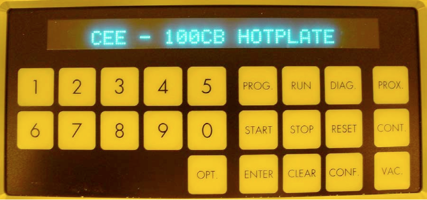
Figure 2. View of the keypad showing the “RESET” and the “PROG” keys. The “OPT” key toggles between the spinner and the hotplate function. This figure shows the “Home” position for the hotplate. This is reached by hitting the “RESET” key and toggling the “OPT” key until this screen appears.

Figure 3. After hitting the “PROG” key, the screen looks like this. It is asking for you to hit a number key to label a new program or call up a previous program.
2. Enter the program number to start your programming. Remember to hit “ENTER” for the program to accept your entry.
3. Enter the temperature for program 1.

Figure 4. Enter the temperature (in C) for program 1.
4. Hit one of the “Method” buttons on the far right side of the keypad. This tells the hotplate program how to handle the wafer contact with the hotplate. There are three modes: 1. “Proximity,” “Contact,” and “Vacuum.” For the Proximity operation, the system has the ability to “float” the wafer like an air hockey puck in close proximity to the hotplate by spewing N2 gas out of the holes in the hotplate surface. The purpose of this method is to “gently” warm the wafer to avoid more sudden temperature changes. 2. The “Contact” mode simply allows the wafer to sit un-aided on the surface of the hotplate and bake like an ordinary simple hotplate. 3. The “Vacuum” mode actually applies vacuum to the hotplate holes and sucks the wafer down onto the surface for better heat conduction and a closer wafer temperature to the actual hotplate temperature.

Figure 5. “Proximity” selection.
5. Input the time you want the wafer to sit suspended on the gas cushion. In this case I use this wafer suspension method to allow me to place the wafer on the hotplate and the wafer to scoot, under gas power, to the centering posts and settle down.

Figure 6. Enter the time in minutes and seconds for the wafer to sit on the gas cushion. Remember to hit enter each time you input a number for the program to go on.
6. Enter another (optional) bake “Method.”

Figure 7. We have selected “CONT” for wafer-hotplate contact.
7. For method 2, enter the bake time for this condition. We consider the first two steps as transitory to nestle the wafer into its home position and quickly but gently warm the wafer for the true bake-under-vacuum suck-down conditions.

Figure 8. Enter the bake time for the “CONT” method.
8. Enter another (optional) bake Method.

Figure 9. We have chosen the third method of hard contact between the wafer and the hotplate for the true bake.
9. Enter the bake time for the vacuum period. After hitting the “ENTER” key, the program returns to the home display and is ready to run.

Figure 10. Enter the bake time for the vacuum method.
Running the Programmed Hotplate
After the hotplate is programmed, baking a wafer is as simple as selecting a bake program, attaining the set-point temperature, and then placing the wafer on the hotplate. The system will beep when the bake time is up. The clever thing about this hotplate is that it is exhausted and the vile vapors out-gassing from the wafer will be captured and sent away without having to first breathe them in to the detriment of our bodies. Therefore keep the lid on the hotplate down all the time. You can lift it up for cleaning.
1. Turn on the CEE system at the red rocker switch by the keypad.
2. Turn on the vacuum pump under the front right edge of the table. The off-on labels are located on the table top at the right front corner.
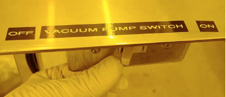
Figure 11. Vacuum pump switch under the right front corner of the table.
3. On the key-pad, select the hotplate function by pressing the “Opt” key until the hotplate title arrives on the readout.
4. Press “Run”
5. Press the program number for your program.
6. Press “Enter”
7. Press “Start.” If the vacuum pump is not turned on at this point, the system will announce it with an error message.
8. The readout will announce when the hotplate has arrived at the programmed set-point temperature.
9. Place the wafer against the two posts on the hotplate. Keep the lid of the hotplate always down to capture the evolving vapors.
10. When the programmed bake time is up, the CEE system will beep loudly! You can then remove your wafer with a tweezers and kill the beeping by hitting “STOP.”
Running the Un-Programmed Hotplate
For a special one time bake operation, you do not have to go to the trouble to program the hotplate. It can be done with a few simple instructions.
- Press the “Opt” key to get into the hotplate program. This is a toggle switch between the hotplate and the spinner.
- Press the “Config” key to open the configuration menu.
- Respond to the Config menu with the number (remember to hit “Enter” after the number for the program to accept your response), of the hotplate program having the temperature you want to bake with. This completes the set-up and the hotplate is now ready to run. This is silly. How do I set an arbitrary temperature I want just for the moment?
- Hit the “Run” key and the number of the program with the temperature you want, and then hit “Enter.”
- Wait for the temperature to stabilize. This could take up to 15 minutes, depending on how far the temperature has to change.
- Hit “Start” to run the bake.
- The Hotplate timer will then start counting up time.
- When the time reaches your target, hit “Stop” and the hotplate will end the run. You can repeat this operation as many times as you need. When a programmed bake is required, just hit “RESET” and “RUN” and the program number (then ENTER), and the hotplate program will begin when you hit “START.”
Spinner programming gives you full control of how you want to dispense and spin your wafers. The control parameters are: 1.) Puddle dispense with no wafer rotation, 2.) Dynamic dispense with the wafer rotating at a selectable speed, 3.) Dispense time, 4.) Rotational acceleration, 5.) Rotational spin speed, 6.) Spin time, 7.) Dispense rate. These parameters are programmed in as many steps per program as you need to accomplish the desired dispense profile.
Spinner programming has display formatting that can be a bit more involved than the simple hotplate instructions. Figure n shows an example.

Figure 12. Example readout format: Program #1, “PG/1”; input description Velocity, “VEL”; Step 0, “/0”, and value “0” with units “RPM”. There are other formats that are more self descriptive and will be explained as they are encountered in this paper.
In this section we will explain spinner programming by using an example program and explaining the steps as they appear.
1. Hit the “RESET” key to bring the controller to its home point readout.
2. Hit the “OPT” button once or twice to access the spinner function.

Figure 13. Home display for the spinner.
3. Hit the “PROG” button to start the programming mode.

Figure 14. Program display with program number inserted.
4. Enter the program number. This means, in this case, hit the number 1 button and then hit “ENTER” for the program to accept the entry. After the “ENTER” key is hit, the programming display moves to the next entry step.
5. Enter “0” for dispense. This causes the syringe to refrain from dispensing fluid at this step.

Figure 15. Enter 0 to not dispense fluid at this step.
6. Enter the spin velocity in RPM. For this program we will dispense resist onto a stationary wafer, so enter “0” for the spin speed.

Figure 16. Enter “0” for no rotation during the dispense step.
7. Enter the ramp acceleration. For this case we are not spinning, so enter “0.”

Figure 17. Enter “0” for no acceleration because we are not rotating.
8. Enter “1” to request dispense from the syringe.

Figure 18. Enter “1” for dispense.
9. Enter the dispense time. This depends on the resist viscosity and the N2 pressure on the syringe. If you have a high viscosity, you may need longer to dispense, or for a low viscosity fluid you will need less time. The N2 pressure on the syringe may need to be increased for a high viscosity fluid. Note that the dispense time, the viscosity of the fluid and the pressure on the syringe all play together to produce a puddle of the right volume to coat the wafer properly.

Figure 19. Enter dispense time. Two seconds in the case of low viscosity (watery) PMMA 495 MW C4 E-Beam Resist. The N2 pressure on the syringe is about 9 psi.
10. Enter the spin speed to spread the resist over the wafer. In this case the spin speed is 3500 rpm.

Figure 20. This display indicates that for spin program one, the first velocity is 3500 rpm. (A “0” will appear in the underline position when you hit “0” again.)
11. Enter the acceleration ramp rate. This is given in units of rpm per second, I think.

Figure 21. Enter the ramp rate in RPM per second.
12. Enter “0” for no dispense in the “NOZZEL# ” request line.

Figure 22. Entering “0” prevents resist dispense for this step.
13. Enter the spin time. There is no dispense during this stage.

Figure 23. Spin time entry.
14. End program. Enter nothing just by hitting “ENTER” again, and the program will insert “END” to stop the programming mode.

Figure 24. End the program by hitting “ENTER.”
15. The program will now return to the spinner home position. This screen looks like that depicted in step 1 of this flow.
This sequence is immensely important. If it is not followed exactly, then there exists the highly probable scene of spewing resist over the CEE, table, floor, you, and having everyone else laughing at you while you spend an hour wiping up resist. / Therefore pay particular attention to the sequence in the following list of steps.
Note particularly the arrangement of N2 lines attached to the syringe dispense body. There are two lines. One is a valve actuated 70 psi line that drives the dispense and suck- back valve roller during dispense. The other is a constant pressure line that delivers a set reduced pressure to the syringe for the purpose of pushing out the resist during dispense.

Figure 25. Note the routing of the N2 pressure lines to the syringe dispense head. The line system that attaches to the “TEE” connector at the top right of the black syringe housing and then trails over to the top of the syringe is the low pressure dispense line. The other line that ends at the top left of the black syringe housing is a valve actuated 70 psi line for the purpose of driving the dispense and suck-back valve roller during dispense.
1. Turn on the vacuum pump before starting. It looks like a standard light switch under the front right edge of the table.
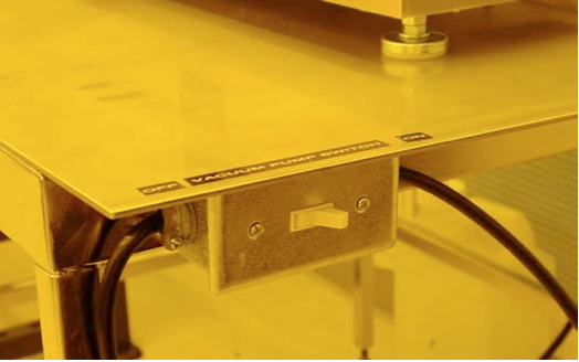
Figure 26. Vacuum Switch on right front edge of table.
2. Turn on the CEE power and establish which hotplate program to run. This starts the hotplate warming while you are loading the resist into the syringe. The “on” button is the little red rocker switch just to the left of the keypad. Press the “Opt” button to select the hotplate. Then press “Run,” and the program number and “Enter.” The hotplate will take about 15 minutes to stabilize at the set point.
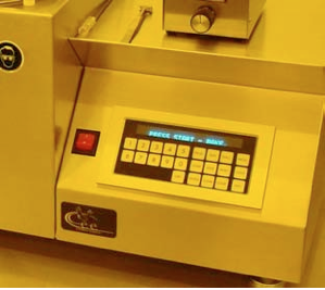
Figure 27. Computer keyboard and readout: Red “On” switch on left of keyboard, “Opt” button at left end of lower key row.
3. Slide the Syringe N2 line valve to OFF. This is the little in-line cylindrical valve in the small, clear Tygon line running to the syringe cap. It has “OFF” and “ON” markings on it. But to be complete here, you turn off the valve by sliding the moveable valve sleeve away from the syringe cap. This prevents a continuing supply of N2 pressure from pushing out any resist that may still be in the syringe and spraying it over everything while you stand there with wide eyes trying to stop it.
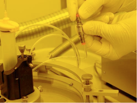
Figure 28. In-Line N2 cutoff valve for preventing unexpected and inadvertent expectoration of resist all over unintended surfaces.
4. Obtain a syringe barrel and label it according to what resist you are going to use. These syringe and needle systems are disposable but expensive. If you can use them for extended times, then we can keep the expense low. In order to do this you can store them with the needle folded up to seal the resist inside. To use the syringe again just replace the needle.
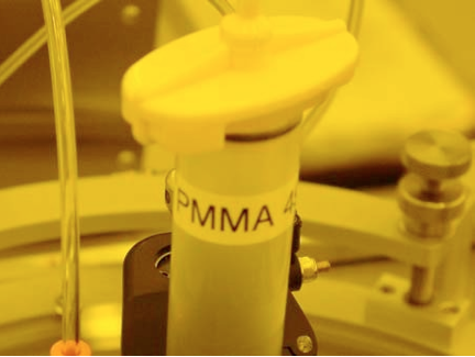
Figure 29. Labeled syringe.
5. Screw the dispensing tip to the end of the Luer syringe barrel.
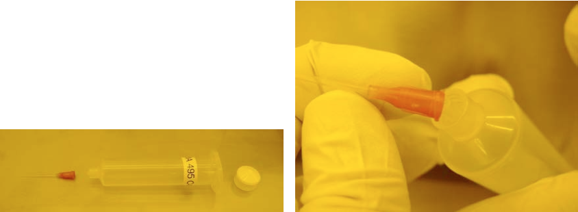
Figure 30. Syringe and needle system. Tip attachment and (white) plug cap.
6. Push down on the suck-back piston and lock it in the ON position with the small lock pin on the outside of the housing. This forces the roller bearing away from squeezing the needle, and allows you to freely insert a new needle into the dispense assembly.
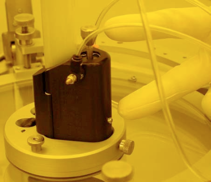
Figure 31. Fingers are pointing to the suck-back piston (top) and locking pin (bottom).
7. Open the syringe housing by unscrewing the knurled knob at the front. This allows the front door of the housing to open, giving you freedom to remove or insert a syringe barrel. There is a fail-safe vent that releases pressure on the syringe barrel as the door opens. You will hear a fizz of N2 leaking out while the door is open. This is normal.
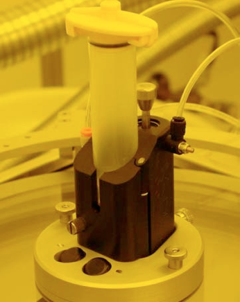
Figure 32. Note the slotted knurled knob at the lower left of the black syringe housing. This releases the syringe for servicing. Also note the knurled knob on the back side of the Al base. This knob releases the black syringe housing for removal and syringe replacement.
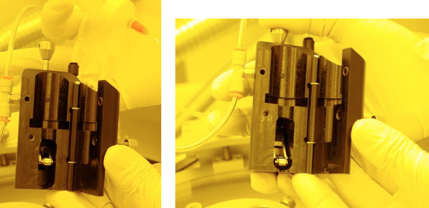
Figure 33. Open syringe housing showing suck-back bearing up (left) and pushed down (right). This rolling action, squeezing the flexible needle tube, acts as a valve and suck- back system to prevent liquid dripping back onto the wafer. The hole in the upper left face of the housing is the pressure safety release to help prevent spewing resist all over everything.
8. Place the next syringe barrel into the housing. Insure that it is seated firmly and as far down towards the tip as possible, and that the flexible needle is seated in the V-groove guide properly. Also, if this is a used needle, rotate the barrel such that the previously squeezed flat needle is oriented so that the roller bearing will press it flat against the opposing wall of the front door. Most importantly, make sure that the Teflon needle is seated in the V-groove as it exits the black syringe housing. Otherwise it can be pinched closed and become nonfunctional.
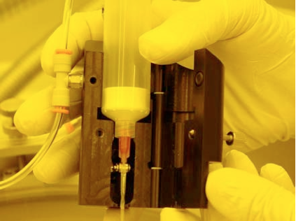
Figure 34. Syringe placement in the housing. Note the flat part of the needle parallel to the roller. This roller should be in the down and locked position for installing the syringe. (The photo shows it in the up position.) Most importantly, make sure that the Teflon needle is seated in the V-groove as it exits the black syringe housing.
9. Close the syringe housing front door and screw in the locking thumbscrew.
10. Release the suck-back piston by pressing down on the piston shaft slightly and releasing it. This will press the roller against the needle, closing the path of fluid flow. This is a key step to prevent drips when you fill the syringe with resist.
11. If the syringe needle is new, press the piston shaft down and release it about 30 times to form the needle shape. This flattens the Teflon tube of the needle so that the resist flow valve action is secure and the suck-back operation is consistent. (Suck-back prevents drips.)
12. Replace the syringe body into the lid assembly. Pay attention to making sure that the flexible needle shaft make it through the hole in the bottom of the receiver and does not become folded up inside the housing.
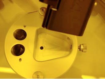
Figure 35. Placing the syringe body in the receiver. Make sure that the flexible needle makes it through the small hole in the bottom of the aluminum base.
13. Pour an appropriate amount of resist into the syringe barrel. Estimate how much resist you will need for the number of wafers you will coat and use only the minimal amount of resist. Any extra may become waste.
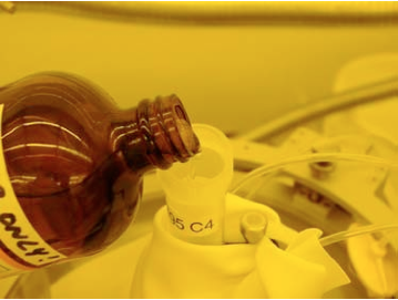
Figure 36. Pouring resist into the syringe. Note the rag to catch spills.
14. Insert the syringe plug and push it down to the top of the liquid level, removing as much trapped air as possible. This prevents resist from getting in to the N2 pressure line and clogging up the works when the lid id opened for wafer transfer.
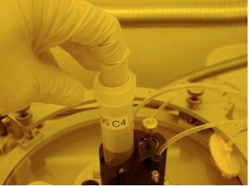
Figure 37. Insert the white plug and push it all the way to the liquid surface, pushing out all the air.
15. Affix the syringe pressure cap onto the syringe. Place it crossways over the top of the syringe barrel, push it in, and then rotate it until it locks against the barrel wings. Hold the barrel of the syringe so it does not twist in the housing and damage the needle.
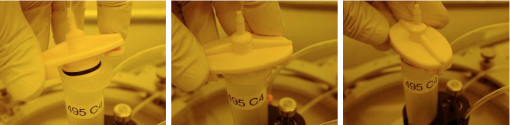
Figure 38. Installing the syringe cap. Fit it crosswise and then twist it until it latches under the wings. Be sure to hold the barrel of the syringe to prevent it from twisting and damaging the needle.
16. Slide the in-line N2 valve to OPEN. This allows the N2 to pressurize the syringe barrel. The pressure remains constant during operation. The syringe is now ready for operation.
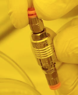
Figure 39. Open the N2 valve by sliding the sleeve towards the syringe.
Coating a wafer requires placing a wafer on the spinner chuck, centering it, and then calling up and running the proper coating program. The wafer alignment is a bit tricky and will be described first.
There are several wafer chucks available. Currently we have a 2 inch diameter chuck and a 4 inch diameter chuck. The 2 inch chuck must be used for 3 inch and 4 inch diameter wafers. The 4 inch chuck can handle 5 and 6 inch wafers. Do not use either of these chucks for any material smaller than the diameter of the chuck. This will cause the resist to be sucked into the vacuum port on the spindle and cause the spinner to degrade and finally fail.
1. Remove the chuck by unscrewing the vented cap head screw in its center.
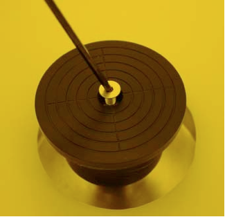
Figure 40. Removing the vented screw to replace the spinner chuck.
2. Carefully lift the chuck off the spindle.
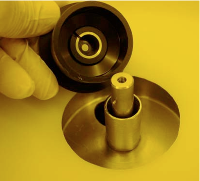
Figure 41. Note the slot in the silver liner in the black chuck and the post on the side of the motor shaft. They must match and seat when attached.
3. Replace the chuck with the chosen size. Note the notch in the chuck receiver cylinder that fits over the motor shaft. It fits over the pin in the shaft to prevent twisting on the shaft. This must fit correctly to prevent damage when the attachment screw is tightened (Figure n).
4. Lightly tighten the chuck screw. Make sure before tightening the screw that the chuck fits properly and does not wobble on the shaft.
5. Return the removed chuck to its proper place.
1. Did you remember to start the hotplate operation before spending all this time fixing the syringe? If not, then do it now and wait until it warms up to the set point temperature. The instructions are way up above here. It will take about 15 minutes or so.
2. Lift the spinner lid and lower the wafer centering arm. Make sure that the alignment posts are vertical. Make sure that you don’t accidentally damage the syringe.
3. Place a wafer onto the chuck and scoot it up against the alignment posts.
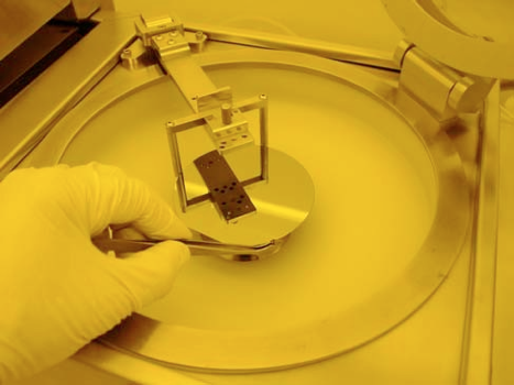
Figure 42. Centering the wafer. Gently slide the wafer against the alignment posts, making sure that the posts don’t move.
4. When the wafer is centered, tilt the alignment posts away from the wafer and lift the alignment arm up until it is in its stable retracted position. The alignment posts that dangle under the arm can be tilted away from the wafer with a little thumb tab on the top of the arm. Make sure that the arm is lifted to a stable position before closing the spinner lid. If it falls back down, it will break your wafer and fling wafer fragments into your face.
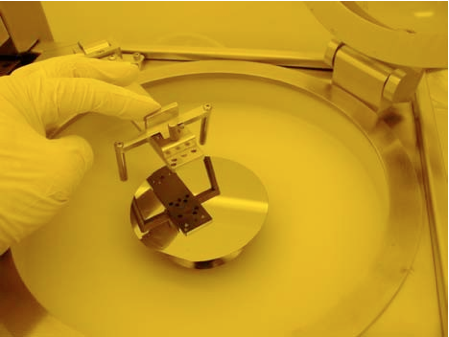
Figure 43. Using the tab on the centering arm, move the alignment posts away from the wafer and then lift the arm up and into its retracted position.
5. Close the spinner lid. Make sure that the syringe tip is vertical and not smashed up against the lid and pointing off center.
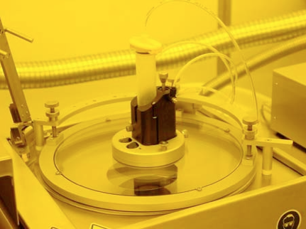
Figure 44. Wafer centering arm retracted and lid closed.
6. Check or set N2 pressure for the syringe to the proper predetermined pressure for dispensing your type of resist. This pressure is set with the knob on the little box sitting on top of the keypad section of the system.
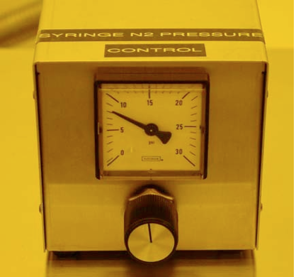
Figure 45. Syringe pressure control. For low viscosity material, use low pressure, for thick viscous fluids, raise the pressure. This constant pressure provides the push to dispense the fluid.
7. Make sure that the in-line N2 valve is open.
Figure 46. Open the N2 valve before starting the dispense process. This is easy to forget, but remember, I told you so right here!!!
8. Push the “Opt” key to select the spinner operation.
9. Push the “Run” key and enter your dispense program number. Press enter after the program number for the system to accept your selection.

Figure 47. Enter the program number for the spin operation.
10. Press Start. The system will rotate the wafer slowly for you to verify that the wafer is centered. If it wobbles more than about 1/16 th of an inch total, recenter the wafer. If you need to recenter it, just lift the lid, lower the alignment arm and push the wafer against the alignment posts. Then check it again by pushing the “0” key as instructed on the readout.


Figure 48. Press “START” to begin the dispense program. The first action will be for the spinner to rotate the wafer slowly so the operator can see if the wafer is truly centered on the chuck. If the total wobble is more than about 1/8 of an inch, recenter the wafer before continuing. Retest centering by hitting “0”.
11. When the wafer is centered, press Start again. This will start the resist dispense and the wafer will rotate at the selected speed or sit stationary according to your program selection. When the dispensing is complete, the wafer will ramp up to the selected spin speed for the selected time. When the wafer comes to a stop, the system will beep loudly and ask for the wafer to be removed.


Figure 49. As the wafer is spinning, the display shows the real time spin speed and the time remaining for the spin cycle. At completion, the controller beeps and displays the instructions to remove the wafer. To stop the beeping, hit “STOP.”
12. Carefully lift the lid and remove the wafer. It will not be held down by vacuum at this point. Be careful not to inadvertently push it off the chuck while trying to pick it up. The system will now be ready to coat another wafer.
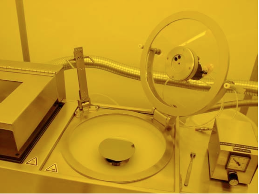
Figure 50. At completion, remove the wafer and close the lid.
13. When you are finished, close the in-line N2 valve. This will help prevent slow drips or accidental discharge of resist by future operators.
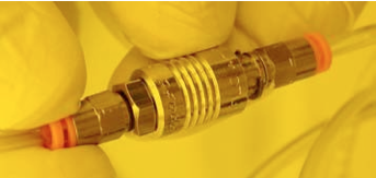
Figure 51. Remember to close the in-line N2 valve to prevent accidents. NOTE: After you finish your coating operation, clean up all the resist in the spin bowl. Please do this in the solvent hood. Also clean up the hood.
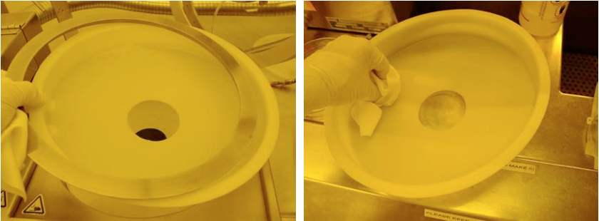
Figure 52. Remove the resist catch-bowl. It just lifts up and the Stainless ring comes right off. Clean it up in the solvent hood with proper solvent for the resist and reinstall it back onto the CEE spinner. (Generally, Acetone will work for most resists.)