
Quintel Mask Aligner Q400-6
This operation manual is prepared by Mr. Sangwon Park and Dr. J-B. Lee in September 2002. Should you have any comments/questions, please email Dr. J-B. Lee.
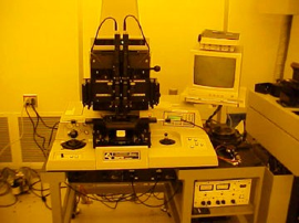
Figure 1. Quintel mask aligner Q4000-6
1. Turn on the vacuum pump ((1) in Fig. 2). Once it is turned on, you can hear pump noise.
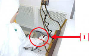
Figure 2. Vacuum Pump Power Switch (Red color)
2. Turn on the main power ((1) in Fig. 3). The red Led will be turned on.
3. Turn on the power switch ((1) in Fig. 4) in the UV power supply. Press the LAMP “START” switch down ((2) in Fig. 4). You have to press and hold it for about 3 seconds . You will notice that “LAMP VOLTAGE” meter ((3) in Fig. 4) goes up around 20 V (If the current mode (I) is selected, change the switch just underneath meter to the voltage (V) mode). The WARMUP period should be AT LEAST 10 minutes. The lamp voltage will be increased to 87 V during the 10 min. WARMUP period.
4. While you are waiting for the power for lamp is warmed up, you can go ahead and program your exposure step. Press the “Enter” key ((1) in Fig. 5). The screen shows “Main Menu” (Fig. 6).
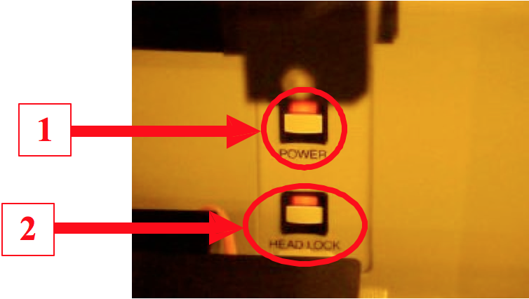
Figure 3. Main Power & Head Lock Switch
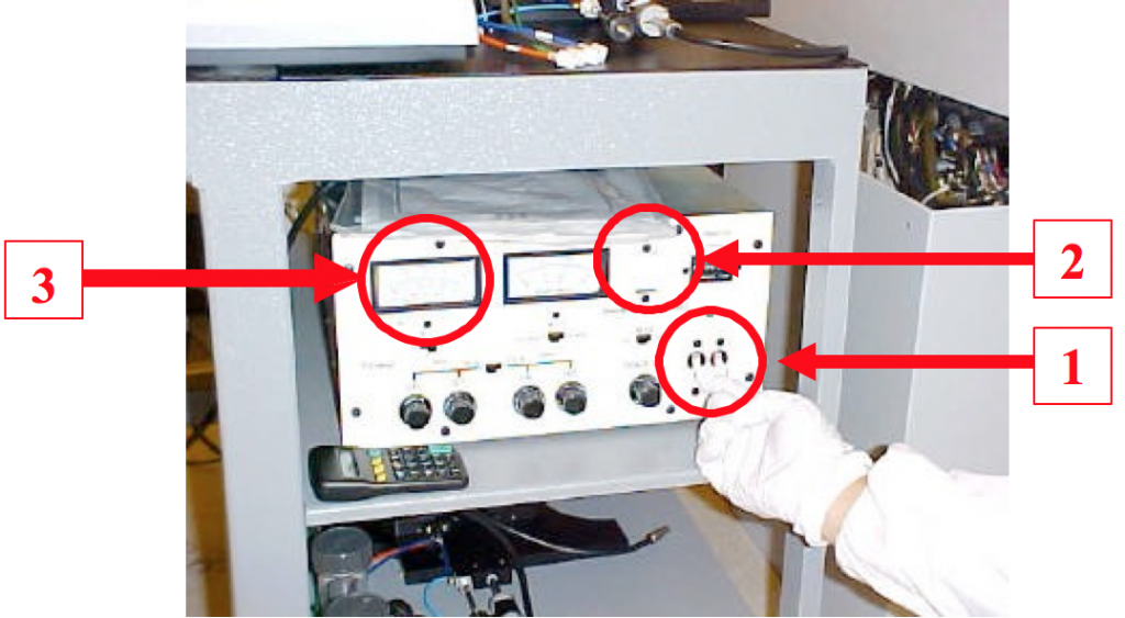
Figure 4. UV Power Supply
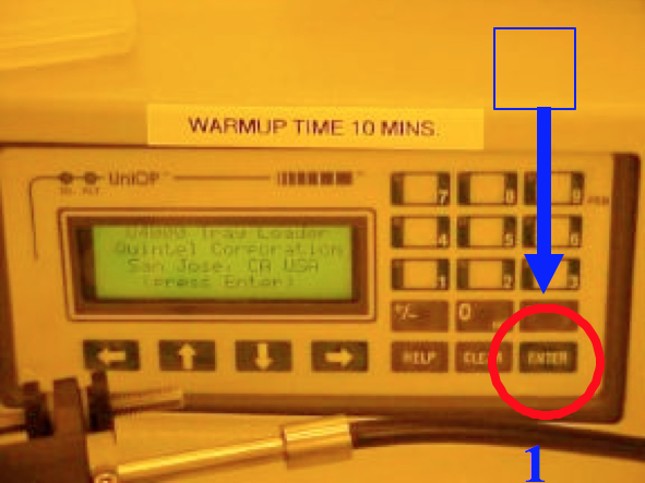
Figure 5. PLC Control Panel
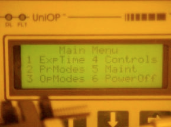
Figure 6. Main Menu Screen
5. Press “2” to go to the “PR (printing) Modes”. Next, select “2” for “Vacuum contact printing mode” (Fig. 7). [PLEASE DO NOT USE OTHER MODES. IF YOU NEED OTHER PRINTING MODES, PLEASE GET AN APPROVAL FROM THE CLEAN ROOM MANAGER]. The menu shows “*” once it is selected (Fig. 7).
6. Press “Enter” (Fig. 5) to go to the “Main Menu” (Fig. 6).
7. Press “3” (Fig. 6) for “OP (operating) Modes”. Make sure “Exp Pressure” is selected (Fig. 8). If selected, it shows “*” in the square bracket. If not, press “1” to select the “Exp Pressure”. Please make sure that you don’t press “1” twice, it will be “unselected” when you press “1” twice. If you did, press “1” one more time to select it. Press “Enter” (Fig. 5) to go to the “Main Menu” (Fig. 6).
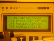
Figure 7. Printing Modes Screen Figure
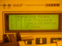
Figure 8. Operating Modes Screen
8. In the Main Menu (Fig. 6), Press “1” for “EXP (exposure) Time”. Press “INS (Insert)” ((1) in Fig. 9) then “Exposure Time” in the screen will be blinking ((2) in Fig. 9). Type in exposure time in “seconds”. {Example: If you want to set your exposure time as 20.5 seconds, press “2 0 . 5” and “Enter”. Currently, the light intensity is set at 17.75 mW/cm 2 @ 365 nm and ~35 mW/cm2 @ 405 nm.} Press “Enter” to go the “Main Menu” (Fig. 6). Press “Enter” again, then the screen shows “Load Wafer” (Fig. 10). NEVER CHANGE THE LIGHT INTENSITY. IT WILL SIGNIFICANTLY REDUCE THE LIFETIME OF THE LAMP. IF YOU EVER NEED TO CHANGE IT, PLEASE GET AN APPROVAL FROM THE CLEAN ROOM MANAGER.
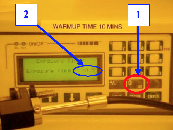
Figure 9. Exposure Time Screen
Figure 10. Load Wafer Screen
9. Press the “HEAD LOCK” button ((2) in Fig. 3) to unlock the Microscope Head ((1) in Fig. 11). Once it is unlocked, the Head Lock Red LED is off and the Microscope Head is free to move. Gently move the “Microscope Head” around 50 degree to your left (blue arrow). Press the “HEAD LOCK” button again so that the “Microscope Head” is locked. Look at the wafer chuck from the top through the mask holder opening, and make sure the wafer chuck is at the center. If not, while you are pressing “Coarse Align” button ((2) in Fig. 11), move the wafer chuck with “Align Stage Joystick” ((3) in Fig. 11).
{CAUTION: MAKE SURE YOU PRESS “COARSE ALIGN” BUTTON WHILE YOU MOVE THE WAFER CHUCK. DO NOT EVER FORCE ON THE JOYSTICK. IT WILL EASILY BREAK.}
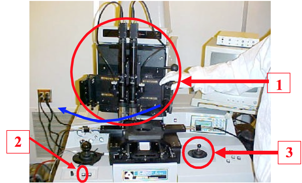
Figure 11. Microscope Head (1), Coarse Align button (2) and Align Stage Joystick (3)
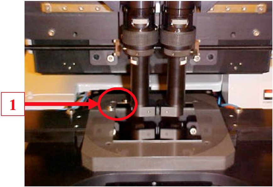
Figure 12. Mask Placement
10. Place your mask (Cr side down) on the mask holder. Make sure top left corner of the mask touches two alignment washers ((1) in Fig. 12). Press “Mask Vacuum” ((1) in Fig. 13). Now mask is set in place and it won’t move.
11. Pull the sample tray out (red arrow, Fig. 14). Next, press “HEAD LOCK” button ((2) in Fig. 3) to unlock the “Microscope Head”. Move the “Microscope Head” back in position (right on top of the wafer chuck). Then, press “HEAD LOCK” on again to lock the “Microscope Head”.
12. Put the “pre-aligner (a piece of plastic)” on the wafer chuck and put your wafer in a manner that wafer’s primary flat touches with the “pre-aligner” (Fig. 15).
13. Once the wafer is pre-aligned, move the “pre-aligner” back (Fig. 16) in position. Next, press the “LOAD” button ((2) in Fig. 13). There is no LED for “LOAD” button. The screen shows “Push Tray In” (Fig. 17).
14. Push sample tray in all the way (opposite direction of the red arrow in Fig. 14). Seconds later, you will hear a little noise that a piston pushes the wafer chuck up to the mask. Now the wafer is brought directly underneath the mask and it is in “Separation” mode. The screen shows “Separation” and “Exposure Time” that you set (Fig. 18). The green LED for SEPARATION will be automatically turned on ((1) in Fig. 19).
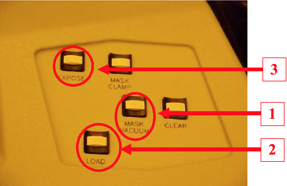
Figure 13. Main Operational Panel
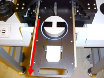
Figure 14. Sample tray
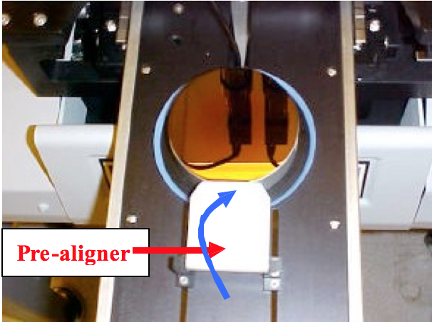
Figure 15. Wafer Pre -Alignment Figure 16. Wafer Loading
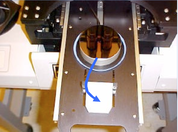
Figure 16. Wafer Loading
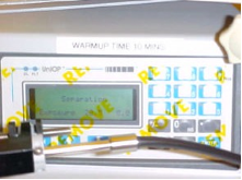
Figure 17. Push Tray In Screen
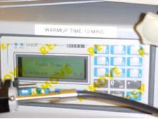
Figure 18. Separation Screen
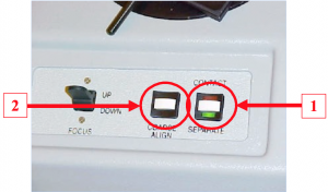
Figure 19. Contact/Separate Mode Switch
15. If you don’t need alignment (i.e., single layer exposure ), you can skip steps 15-18. Go To the Step 19. Turn the MV-200 power on ((1) in Fig. 20). Turn the monitor power on ((2) in Fig. 20). Turn the knob from “OFF ” to “MIC (microscope)” ((1) in Fig. 21). Now, microscope light is illuminated and you can see the image of the mask and the wafer through the monitor. Adjust microscope illumination intensity ((2) in Fig. 21) as necessary. Move the microscope objective in x (each objective moves independently, (1) in Fig. 22) and y (both objectives will be moved, (2) in Fig. 22) direction as necessary. If the knobs ((3) in Fig. 22) are tightened, loose them slightly and move the microscope objectives as necessary. Once the alignment is done, make sure the knobs are tightened. If they are not tightened, what you see through the monitor and what you will get at the wafer may be different.
16. Move the mask/wafer stage together as necessary with “Scan Stage Joystick” ((1) in Fig. 23). {CAUTION : YOU HAVE TO PRESS BUTTON ((4) in Fig. 21) ON TOP OF THE SCAN STAGE JOYSTICK WHEN YOU MOVE THE JOYSTICK. IF YOU DON’T PRESS THE BUTTON AND FORCE TO MOVE THE JOYSTICK, IT WILL BREAK.}
17. Turn the “coarse focus” ((1) in Fig. 24) and the “fine focus” ((2) in Fig. 24) as necessary. Zoom in and out as necessary ((3) in Fig. 24). The monitor will show you features on the mask and on the wafer. {NEVER ATTEMPT TO CHANGE THE EYEPIECES. IN MOST CASES, YOU WILL NEVER NEED TO CHANGE THEM. IF NEEDED, PLEASE CONTACT THE CLEAN ROOM MANAGER.}
18. Move the wafer chuck with “Align Stage Joy Stick” ((2) in Fig. 23) to align features on your mask and on the wafer. While you press “Coarse Align” button ((2) in Fig. 19) and move the “Align Stage Joystick”, it will give you a coarse alignment. While you don’t press the “Coarse Align” button and move the “Align Stage Joy Stick”, it will give you a fine alignment. Again, do not force the joystick over the range. NOW YOUR SAMPLE AND THE MASK IS ALIGNED. AND YOU ARE READY FOR THE “EXPOSURE STEP”.
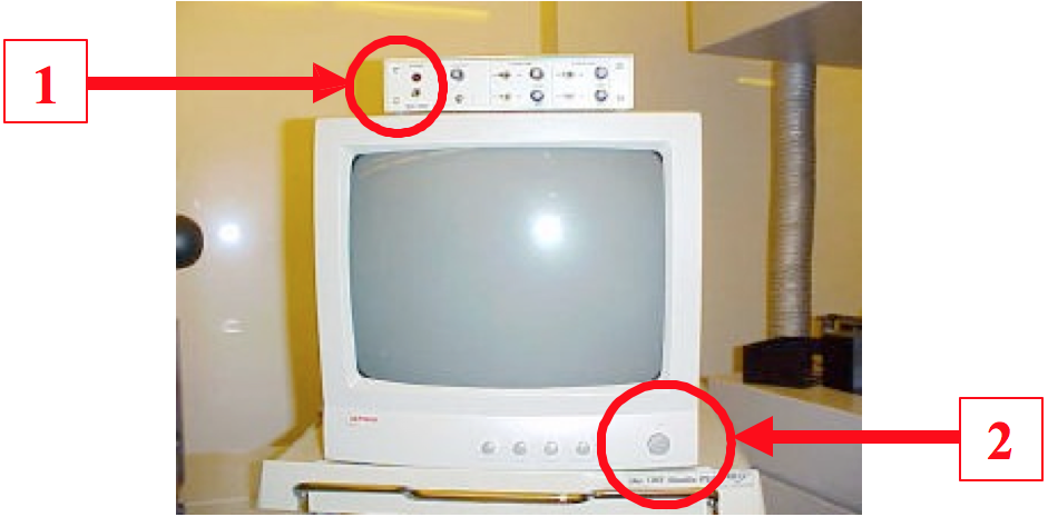
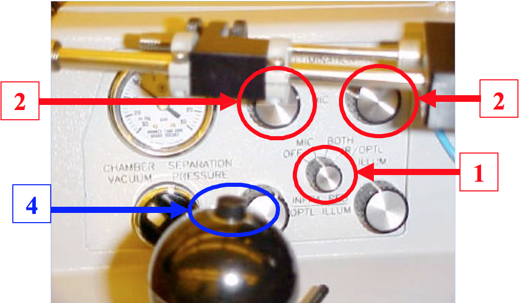
Figure 21. Illuminator Adjustment
19. Press the “CONTACT” button ((1) in Fig. 19). Contact red LED will be turned on. Press “EXPOSE” button ((3) in Fig. 13). Then the Exposure Head will be automatically moved in and the exposure will be carried out . After the exposure is done, the screen shows “UNLOAD WAFER”. Pull the sample tray out (red arrow in Fig. 14) and take your exposed wafer out. Then, press the “MASK VACUUM” button ((1) in Fig. 13) to turn off the mask vacuum and take your mask out.
20. If you don’t need alignment (i.e., single layer exposure ), you can skip step 20. Go To the Step 21. If you used microscope for alignment, turn the knob from “MIC” to “OFF” ((1) in Fig. 21) to turn off the microscope illumination. Turn MV-200 ((1) in Fig. 20) and monitor off ((2) in Fig. 20).
21. Press “ENTER” (Fig. 5) to go to the “Main Menu”. Press “6” for “PowerOff” (Fig. 6). It will be turned off in a few seconds. WAIT! THAT’s NOT ALL.
22. Wait for another 5 minutes, and then turn the “Illumination Controller” off ((1) in Fig. 4). During this period, the UV Lamp is cooled. If you turn the “Illumination Controller” off right after your exposure, IT WILL SIGNIFICANTLY REDUCE LAMP LIFETIME.
23. Turn the “Vacuum pump” off ((1) in Fig. 2). Now, IT’S ALL DONE !!!!
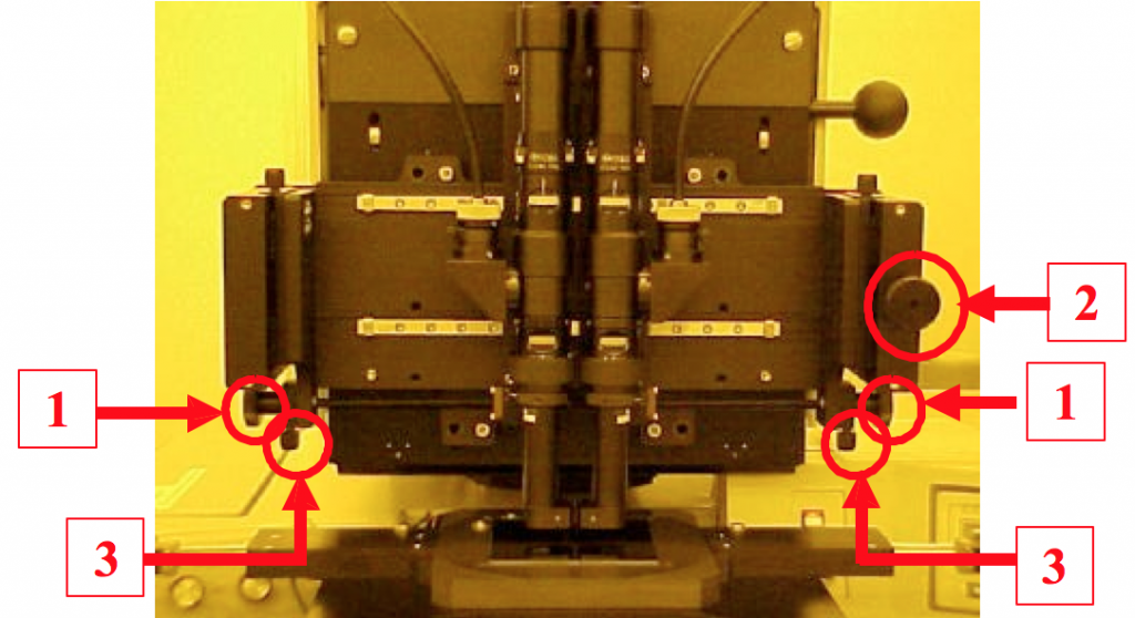
Figure 22. Front -view of Microscope Head
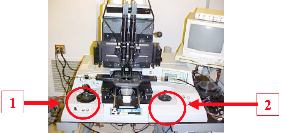
Figure 23. Joysticks
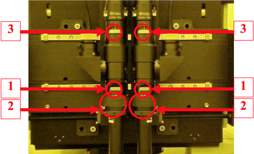
Figure 24. Microscope